3
Connections Operations Explanation of terms Troubleshooting Specifi cations Index
ENGLISH
Part namesGetting started
Part names
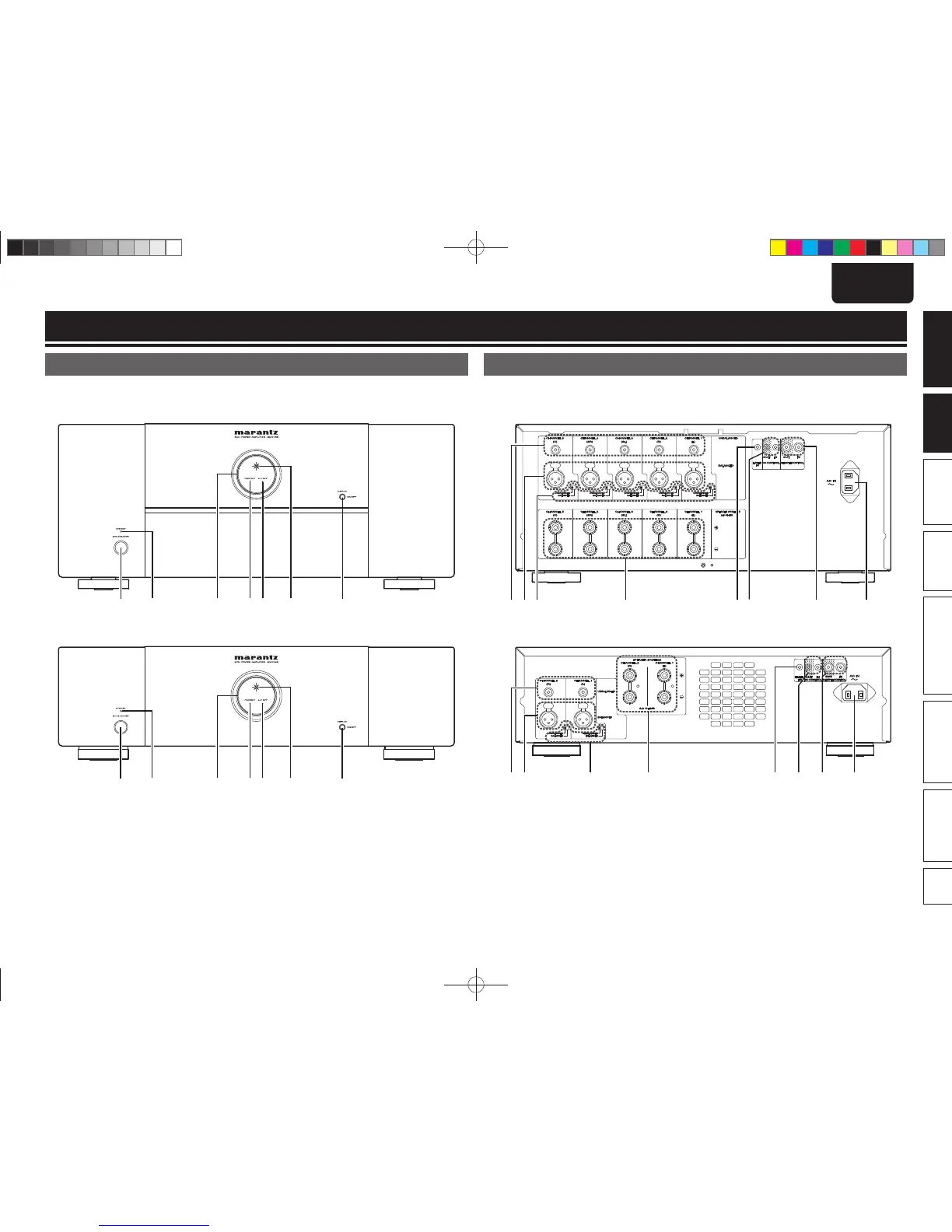
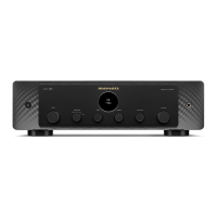
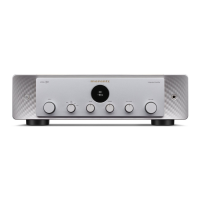
Front panel
For buttons not explained here, see the page indicated in parentheses ( ).
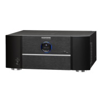
n MM7055
q uwrte y
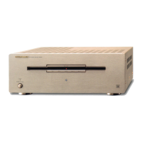
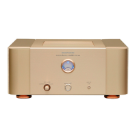
n MM7025
q uwrte y
q Power switch (ON/STANDBY) ···················· (9)
w STANDBY indicator ······································ (9)
e Illumination lamp ········································· (9)
r Protection indicator (PROTECT) ············ (9, 10)
t Auto power off indicator (A.P.OFF) ············ (9)
y Power indicator ············································ (9)
u DISPLAY button ············································ (9)
• Press this button to turn the illumination lamp
ON/OFF.
• You can set the auto standby function by
pressing and holding this button for more than
5 seconds.
Rear panel
See the page indicated in parentheses ( ).
n MM7055
w e r iuytq
n MM7025
w e r iuytq
q RCA input connectors (UNBALANCED) ····· (6)
w XLR input connectors (BALANCED) ··········· (6)
e Input selector ················································ (4)
r Speaker terminals
(SPEAKER SYSTEMS) ·································· (6)
t Flasher input terminals
(FLASHER IN) ················································ (8)
y DC CONTROL jacks ······································ (8)
u REMOTE CONTROL connectors ·············· (7, 8)
i AC inlet (AC IN) ············································· (7)
MM70557025NENG5th0729.indd3MM70557025NENG5th0729.indd3 2010/07/2921:49:372010/07/2921:49:37