25
ADJUSTMENT
Idling Current Alignment
(1) Each of the measurement points are provided with the two test points. Set a digital Voltage meter to DC voltage
input, connect the meter to the test points at both contact points.
(2) After the setup above, turn on the main switch.
(3) Adjust variable resistors (VR20 - VR50) according to the digital voltmeter readings. The target setting value is the
following table for each channel.
Settings : No-signal of input
Speaker out — No Load
Top lid — OPEN
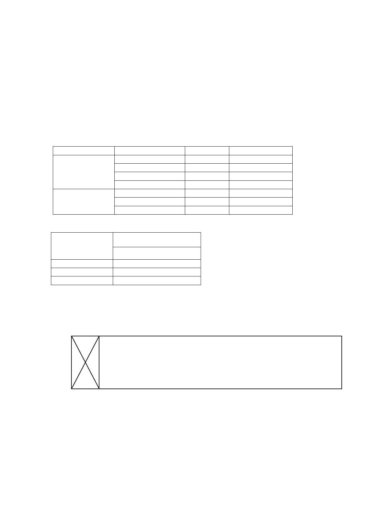
Measurement Point
AMP PWB Channel Adjustment VR Measurement Point
Front side
AMP PWB
SL (CHANNEL 3) VR20 CN20
SR (CHANNEL 4) VR30 CN30
SBL (CHANNEL 5) VR40 CN40
SBR (CHANNEL 6) VR50 CN50
Rear side
AMP PWB
L (CHANNEL 1) VR50 CN50
R (CHANNEL 2) VR40 CN40
C (CHANNEL 7) VR30 CN30
Time Table of Idling Current Rise
After Turning ON
Ambient temperature
20 to 30 degrees centigrade
Measurement Voltage
10 min. 1.5 mV ± 0.2 mV
20 min. 1.5 mV ± 0.2 mV
30 min. 1.5 mV ± 0.2 mV
REAR SIDE
FL
(CHANNEL 1)
VR50
CN50
SL
(CHANNEL 3)
VR20
CN20
SR
(CHANNEL 4)
VR30
CN30
SBL
(CHANNEL 5)
VR40
CN40
FR
(CHANNEL 2)
VR40
CN40
POWER AMP MODULE
MAIN HEAT SINK
FAN
FRONT SIDE
C
(CHANNEL 7)
VR30
CN30
SBR
(CHANNEL 6)
VR50
CN50
 Loading...