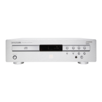
SA-14
410K855010 KKI
First Issue
2001. 03
Service
Manual
R
SA-14
Please use this service manual with referring to the user guide ( D.F.U. ) without fail.
Printed in Japan
SA14/
F1N, /C1G, /S1G,/U1G, /U1B
Super Audio CD Player
TABLE OF CONTENTS
SECTION PAGE
1. MAIN UNIT
1.1 TECHNICAL SPECIFICATIONS ......................................................................................................... 1-1
1.2 TEST MODE ........................................................................................................................................ 1-2
1.3 BLOCK DIAGRAM ............................................................................................................................... 1-3
1.4 WIRING DIAGRAM ............................................................................................................................. 1-5
1.5 SCHEMATIC DIAGRAM ...................................................................................................................... 1-7
1.6 PARTS LOCATION ........................................................................................................................... 1-19
1-23
1-24
2. CDM-15M ( SACD MODULE )
2.1 REMOVING AND REINSTALLING THE MAIN PARTS ...................................................................... 2-2
2.2 BLOCK DIAGRAM ............................................................................................................................... 2-5
2.3 SCHEMATIC DIAGRAM ...................................................................................................................... 2-9
2.4 PARTS LOCATION ........................................................................................................................... 2-13
2.5 IC DATA ............................................................................................................................................ 2-17
2.3 EXPLODED VIEW AND PARTS LIST ............................................................................................... 2-36
2.4 ELECTRICAL PARTS LIST ............................................................................................................... 2-37
SACD CD
PAUSESTOP
DISPLAY
SACD/CD
PLAY
SUPER AUDIO CD PLAYER SA-14
OPEN/CLOSE
POWER
TRACK
RND
PROGRAM TOTAL
PLAY
REP 1
............................................................................................... 1.9 EXPLODED VIEW AND PARTS LIST
......................................................................................................... 1.7 ELECTRICAL ADJUSTMENTS
1.8 IC DATA
............................................................................................................................................
1-26
1.10 ELECTRICAL PARTS LIST .............................................................................................................. 1-29