2
Digital Voltmeter
Rch
V
Digital Voltmeter
Lch
V
PH81
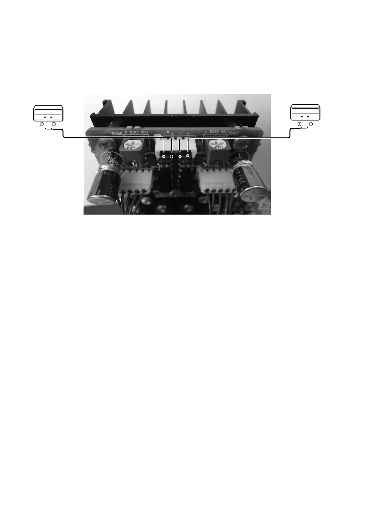
3. ALIGNMENTS
Idling Current Adjustment (for PHONES power amp.)
Set the power voltage to rated voltage for this adjustment.
Adjust the Idling Current with the variable resistor RH87
and RH88 on the PWB (PH81).
1. Turn off the power.
2. Connect Digital Voltage to No. 1 to No.4 pin of JH83.
(The connection is follows)
No. 1 pin (Rch -) : Digital Voltage "
-"
No. 2 pin (Rch +) : Digital Voltage "+"
No. 3 pin (Lch -) : Digital Voltage "-"
No. 4 pin (Lch +) : Digital Voltage "+"
3. Before turning on the power, RH87 and RH88 have been
counter clockwise turned with the adjustment driver.
4. Turn on the power.
5. After turn on the power 3 minutes, With seeing the digital
voltage meter turn the variable resister clockwise slowly
to adjust the idling current. Idling adjustment with RH87
(RH88).
• Turn RH87 (RH88) clockwise to increase the idling
current.
• The adjustment value of idling current is
"10mV(10mA) ±0.5mV(0.5mA)" each.
6. After turn on the power 5 minutes, repeat the Same
procedure as 5.
• The adjustment value of idling current is
"10mV(10mA) ±0.5mV(0.5mA)" each.
7. Idling current decreases with the temperature rise inside
the unit, and it is set to about 9mV (9mA) of setting value
in about 30 minutes after turn on the power.
Adjustment is completed.
8. Remove connection cable, attach the top cover.
アイドリング電流調整(ヘッドフォンアンプ用)
調整時は必ず電源電圧を定格電圧に合わせてください。
PH81基板上の半固定抵抗RH87とRH88でアイドリング電流を
調整します。
1. 電源をOFFします。
2. PH81基板のJH83にデジタルボルトメーターを接続しま
す。
接続は下記です。
1番ピン(Rch -) : デジタルボルトメータ "-"
2
番ピン(Rch +) : デジタルボルトメータ "+"
3
番ピン(Lch -) : デジタルボルトメータ "-"
4
番ピン(Lch +) : デジタルボルトメータ "+"
3.
電源を投入する前に半固定抵抗RH87とRH88を、調整ドラ
イバーで反時計方向に回しきってください。
4. 電源をONします。
5. 電源を投入後3分経過したら、PH81基板のJH83に接続した
デジタルボルトメーターの電圧値を監視しながら、半固定
抵抗
RH87(RH88)をゆっくりと時計向に回してください。
• RH87とRH88を時計方向に回すとアイドリング電流が増
加します。
• アイドリング電流の調整値はそれぞれ
"10mV(10mA) ±0.5mV(0.5mA)" にします。
6. 電源投入から5分経過後、上記5.の手順でもう一度調整しま
す。
• アイドリング電流の調整値はそれぞれ
"10mV(10mA) ±0.5mV(0.5mA)"にします。
7. 調整週後、セット内の温度上昇に伴いアイドリング電流が
減少します。電源投入
30分後で設定値の"約9mV(9mA)"に
なります。
以上で調整は完了です。
9. デジタルボルトメーターの接続を外し、トップカバーを取付
けます。
 Loading...