2. POWER AMPLIFIER ADJUSTMENT
Idling Current Alignment
1. Each of the measurement points are provided with the two test points. Set a digital Voltage meter to DC voltage input,
connect the meter to the test points at both contact points.
2. After the setup above, turn on the main switch.
3. Adjust variable resistors (VR51 - VR61) according to the digital voltmeter readings. The target setting value is the
following table for each channels.
Settings :
Master Volume — Minimum
Speaker out — No Load
Top lid — OPEN
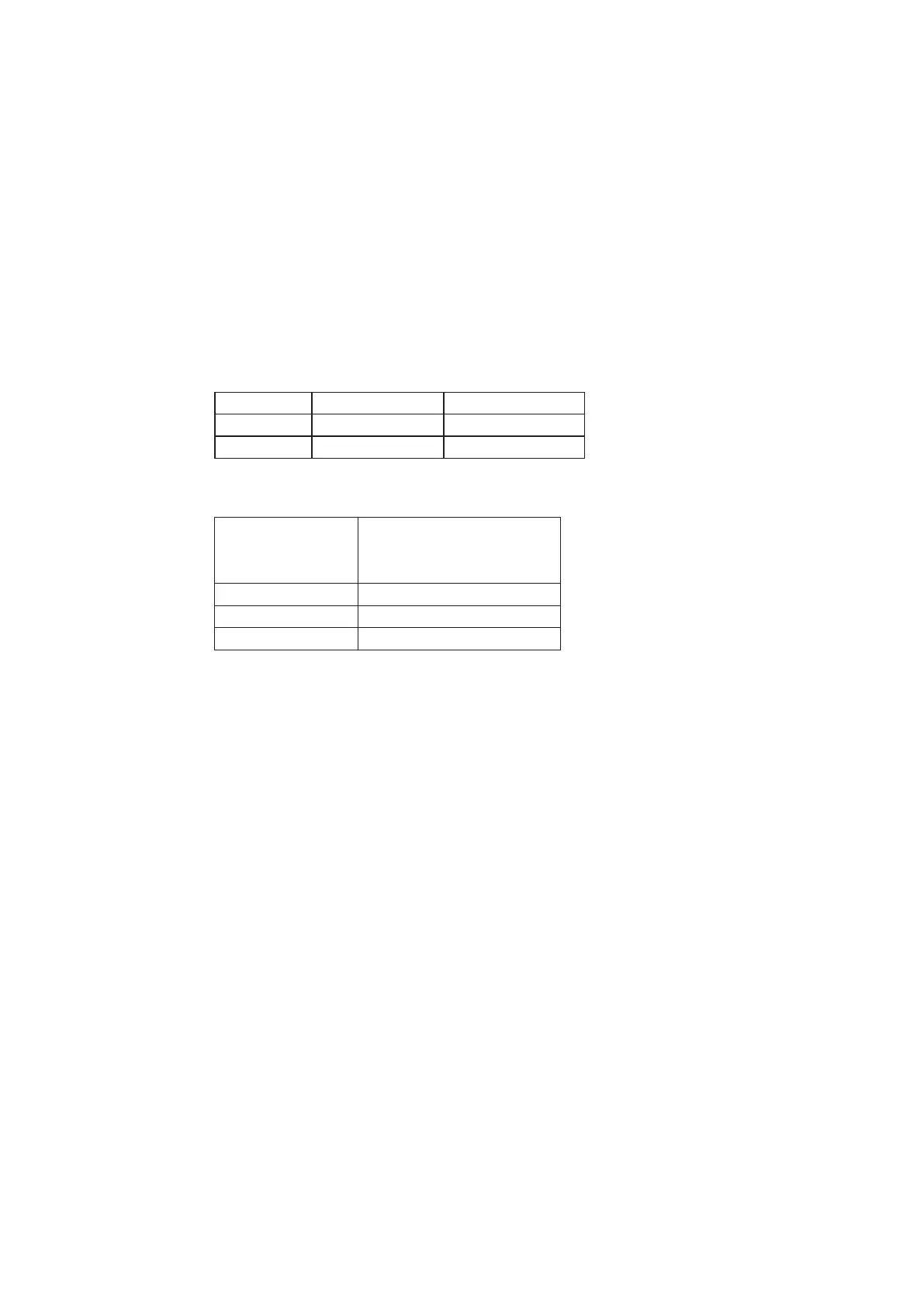
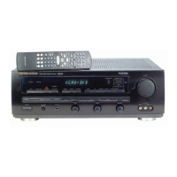
Time Table of Idling Current Rise
Channel Alignment Point Measurement Point
L ch VR51 CN51
R ch VR61 CN61
After Turning ON
Ambient temperature
20 to 30 degrees centigrade
Measurement Voltage
10 min. 5 mV ± 0.5 mV
20 min. 5 mV ± 0.5 mV
30 min. 5 mV ± 0.5 mV