Do you have a question about the Marantz SR4400 and is the answer not in the manual?
| Audio Channels | 6.1 |
|---|---|
| Dolby Processing | Dolby Digital, Dolby Pro Logic II |
| Video Inputs | composite, s-video |
| Radio Tuner | AM/FM |
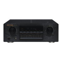
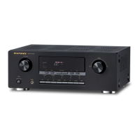
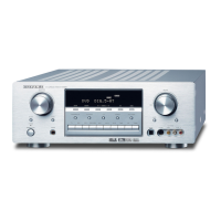
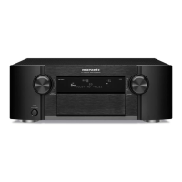
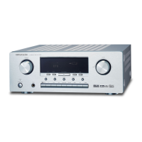
| Type | AV Receiver |
| HDMI | No |
| Component Video Inputs | 2 |
| Total Harmonic Distortion | 0.08% |
| DTS Processing | DTS, DTS Neo:6 |
| Frequency Response | 10Hz-100kHz |
| Input Sensitivity | 200mV |
| Signal-to-Noise Ratio | 105 dB |
| Inputs | digital coaxial, digital optical |
| Weight | 12kg |
Instructions for ordering replacement parts from Marantz subsidiaries or agents.
Safety test procedure for checking resistance after servicing to prevent electrical hazards.
Specifications for the FM tuner, including frequency range, sensitivity, and distortion.
Specifications for the AM tuner, including frequency range, sensitivity, and distortion.
Specifications for audio output power, input sensitivity, and frequency response.
Specifications for video input/output levels, response, and signal-to-noise ratio.
General specifications including power requirements, consumption, and weight.
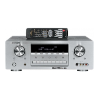
List of included accessories such as remote control, batteries, and antennas.
Explanation of DTS (Digital Theater Systems) for multi-channel digital audio.
Description of DTS Neo:6 technology for matrix surround sound decoding.
Details on DTS-ES Extended Surround, a multi-channel digital signal format.
Explanation of Dolby Digital EX and Pro Logic II for surround sound processing.
Description of SRS Circle Surround II technology for multi-channel surround sound.
Procedure for adjusting idling current using a voltage meter and test points.
Procedure for checking processor version and FL display segments via button combinations.
Steps to reset the unit's memory to default status by pressing specific buttons.
List of resistors with their codes, values, and types.
List of capacitors with their codes, values, and types.
Common abbreviations and marks used in the parts list and schematics.