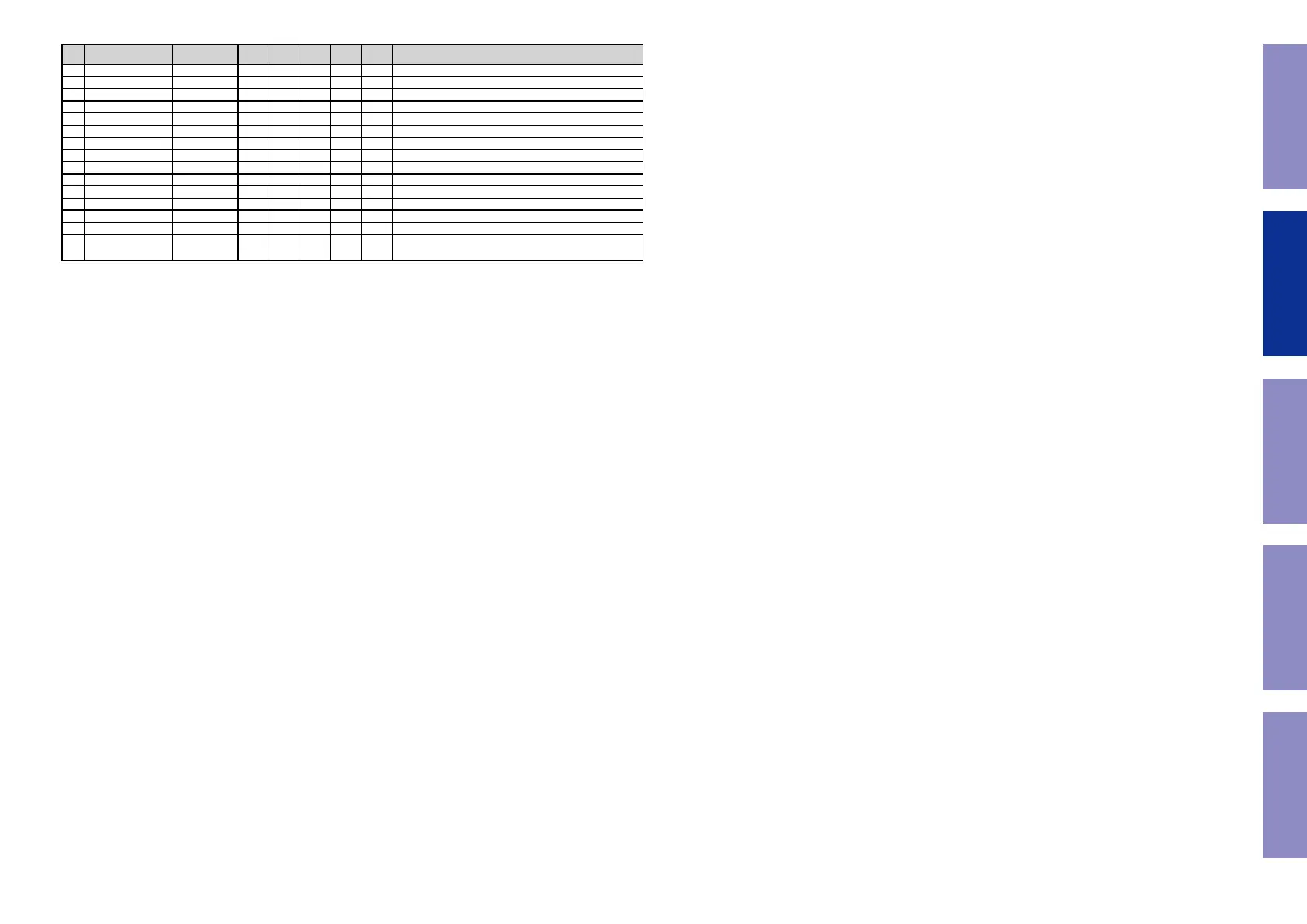
Pin Pin Name Symbol I/O Pu/Pd STBY STOP
CEC
STBY
Function
162 VSS VSS - - - - Ground pin
163 P90/TXD7/AN114 TEMP_SENSOR I
NET3.3VPu
I L I Temperature sensor input pin (for SRM)
164 VCC VCC - - - - Power supply pin
165 P47/IRQ15-DS/AN007 788_3_HAINT I
CEC3VPu
Z - HDMI Rx (MN864788) audio interrupt signal det
166 P46/IRQ14-DS/AN006 CURRENT_DET I
Pd
I L I Current level monitor pin (A/D converter)
167 P45/IRQ13-DS/AN005 AMPSIGDET I
Pd
I L I Signal level monitor pin (AD converter)
168 P44/IRQ12-DS/AN004 MODE I I I I Region setting pin
169 P43/IRQ11-DS/AN003 KEY3 I
M3VPu
I I I Key control signalinput pin (When standby mode,set to inturrupt)
170 P42/IRQ10-DS/AN002 KEY2 I
M3VPu
I I I Key control signalinput pin (When standby mode,set to inturrupt)
171 P41/IRQ9-DS/AN001 KEY1 I
M3VPu
I I I Key control signalinput pin (When standby mode,set to inturrupt)
172 VREFL0 VREFL0 - - - - Ground pin
173 P40 ADC_RST O I L I A/D convertor(AK5358) reset control pin
174 VREFH0 VREFH0 - - - - Power supply pin
175 AVCC0 AVCC0 - - - - Power supply pin
176 P07/IRQ15
COMP_DET
(SR5014)
/NC
(S950H/
X2600H/NR1710)
I
M3VPu
I I I Component video signal detect pin
Before Servicing
This Unit
Electrical Mechanical Repair Information Updating
58