b
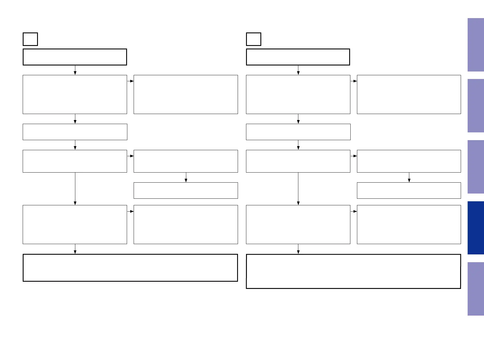
These instructions refer to the VIDEO PCB unless otherwise specied.
b
These instructions refer to the VIDEO PCB unless otherwise specied.
Input
CVBS
Input
COMPONENT
B C
Check the settings of each IC.
Are the following voltages set?
DIGITAL PCB
BN21A - 1 pin : Hi (3.3 V)
BN21A - 2 pin : Hi (3.3 V)
BN21A - 3 pin : Lo (0 V)
Check the settings of each IC.
Are the following voltages set?
DIGITAL PCB
BN21A - 5 pin : Lo (0 V)
BN21A - 4 pin : Hi (3.3 V)
Extend the DIGITAL PCB using the jig. Extend the DIGITAL PCB using the jig.
Is the power voltage being output correctly?
V+5V : C5107 : + side
V-5V : C5109 : - side
Is the power voltage being output correctly?
V+5V : C5107 : + side
V-5V : C5109 : - side
Check the connection between the SIDE CON-
NECTOR PCB and the VIDEO PCB.
Check the connection between the SIDE CON-
NECTOR PCB and the VIDEO PCB.
The regulator part of REG_SPK PCB is faulty. The regulator part of REG_SPK PCB is faulty.
Is a signal being output from the video amplier?
CVBS : J5018
Is a signal being output from the video amplier?
COMP-Y : J5002
COMP-CB : J5001
COMP-CR : BN21B 11pin
• Check the IC511 power voltage and check the
soldering of the surrounding circuits.
• The pattern between IC511 and BN21B is faulty.
• Check the IC516 power voltage and check the
soldering of the surrounding circuits.
• The pattern between IC516 and JK515/BN21B is
faulty.
DIGITAL PCB faulty. DIGITAL PCB faulty.
• Check the connection between the FRONT CONNECTOR PCB and the VIDEO PCB.
• Check the soldering of BN21B on the VIDEO PCB.
• Check the soldering of BN21A on the DIGITAL PCB.
• Check the soldering of CN21A and CN21B on the FRONT CONNECTOR PCB.
• Check the connection between the FRONT CONNECTOR PCB and the VIDEO PCB.
• Check the soldering of BN21B on the VIDEO PCB.
• Check the soldering of BN21A on the DIGITAL PCB.
• Check the soldering of CN21A and CN21B on the FRONT CONNECTOR PCB.
• Check the soldering of JK515(E3) on the VIDEO PCB.
q q
w w
e e
r r
NO NO
NO NO
NO NO
YES
YES
YES
YES
YES
YES
NO NO
88
Caution in
servicing
Electrical Mechanical Repair Information Updating
 Loading...