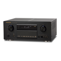
The Marantz SR800 is a stereophonic receiver designed to provide high-quality audio reproduction. It integrates an AM/FM tuner, a preamplifier, and a power amplifier into a single unit, offering a comprehensive solution for home audio systems. The receiver is built with superior design and selected high-grade components to ensure optimal performance and sound quality.
Function Description:
The Marantz SR800 serves as the central hub for an audio system, allowing users to select and amplify various audio sources. Its primary functions include:
- AM/FM Tuner: The receiver features a built-in tuner for receiving both AM and FM radio broadcasts. This includes stereo FM reception, with specific alignment procedures for FM IF, FM RF, muting circuit, and multiplex to ensure clear and accurate radio playback.
- Preamplifier: It includes inputs for various audio sources such as a phono (turntable), auxiliary devices, and tape decks. The preamplifier section allows for source selection, volume control, balance adjustment, and tone control (bass and treble) to customize the sound output.
- Power Amplifier: The integrated power amplifier boosts the audio signals to drive loudspeakers. It supports two speaker systems, allowing for flexible speaker configurations.
- Headphone Output: A dedicated headphone jack is provided for private listening.
- Tape Monitor Function: The receiver includes a tape monitor loop, enabling users to connect and monitor tape recorders or other external audio processors.
Important Technical Specifications:
The Marantz SR800 boasts a range of specifications that highlight its audio performance:
Audio Section:
- Power Output (DIN, 4 Ohm, per channel): 27 W
- Power Output (FTC American Standards, 4 Ohm, per channel): 18 W
- Total Harmonic Distortion (at rated power output): 0.3% (4 Ohm), 0.1% (8 Ohm)
- I.M. Distortion (at rated power output, 250 Hz and 8 kHz mixed, amplitude ratio 4:1): 0.3% (4 Ohm), 0.1% (8 Ohm)
- Power Output (DIN, 8 Ohm, per channel): 22 W
- Power Output (FTC American Standards, 8 Ohm, per channel): 15 W
- Power Bandwidth: 10 Hz ~ 40 kHz
- Damping Factor (8 Ohm): 44 (40 Hz), 45 (1 kHz), 42 (12.5 kHz)
- Frequency Response (Phono RIAA): ±1.0 dB
- Frequency Response (Aux): 18 Hz ~ 30 kHz (±1 dB)
- Signal-to-Noise Ratio (Phono): 70 dB
- Signal-to-Noise Ratio (Aux): 80 dB
- Phono Input Impedance: 47 k ohms
- Phono Input Capacitance: 100 pF
- Phono Input Sensitivity: 2.7 mV
- Phono Overload Margin: 30 dB
- Aux Input Impedance: 20 k ohms
- Aux Input Sensitivity: 160 mV
- Phono Equivalent Input Noise: 1.4 μV
- Phono Dynamic Range: 100 dB
- Channel Balance (0 to -40 dB/40 Hz ~ 16 kHz): Phono 2.5 dB, Aux 2.0 dB
- Interchannel Crosstalk (Phono 1 kHz): 35 dB
- Interchannel Crosstalk (Aux 1 kHz): 43 dB
- Interchannel Crosstalk (Tape 1 kHz): 50 dB
- Intersource Crosstalk (Worst Point 1 kHz): 44 dB
- Output Voltage (Tape Out, 1 kHz): 500 mV
- Output Impedance (Tape Out, 1 kHz): 500 ohms
- Headphone Jack Load Impedance: 8 ohms
FM Tuner Section:
- Frequency Range: 87.5 ~ 108 MHz
- Usable Sensitivity (40 kHz Deviation, 98 MHz, Mono, S/N 26 dB): 1.7 μV
- Usable Sensitivity (40 kHz Deviation, 98 MHz, Stereo, S/N 46 dB): 45 μV
- Alternate Channel Selectivity (98 MHz±300 kHz): 50 dB
- Image Response Rejection (98 MHz): 54 dB
- IF Rejection (98 MHz): 100 dB
- Spurious Response Rejection (98 MHz): 90 dB
- AM Suppression (98 MHz): 25 dB
- Signal-to-Noise Ratio (98 MHz, Unweighted Mono): 62 dB
- Signal-to-Noise Ratio (98 MHz, Unweighted Stereo): 55 dB
- Signal-to-Noise Ratio (98 MHz, Weighted Mono): 62 dB
- Signal-to-Noise Ratio (98 MHz, Weighted Stereo): 55 dB
- Pilot Signal & Subcarrier Rejection (19 kHz): 58 dB
- Pilot Signal & Subcarrier Rejection (38 kHz): 58 dB
- Total Harmonic Distortion (98 MHz, Mono): 0.2%
- Total Harmonic Distortion (98 MHz, Stereo): 0.4%
- Frequency Response (30 Hz ~ 15 kHz): +0.5 dB, -2 dB
- Separation (Stereo): 45 dB
- Channel Balance: 0.5 dB
- Output Voltage (1 kHz): 600 mV
- Output Impedance (1 kHz): 4.4 k ohms
- Acceptable Load Impedance (1 kHz): 47 k ohms
- Antenna Terminals (Balanced): 300 ohms
- Antenna Terminals (Unbalanced): 75 ohms
MW Tuner Section:
- Frequency Range: 515 ~ 1650 k Hz
- Usable Sensitivity (26 dB S/N 30% Mod., 1 MHz): 30 μV
- Selectivity (1 kHz±9 kHz): 20 dB
- Image Rejection (1 MHz): 40 dB
- IF Rejection (1 MHz): 40 dB
- Spurious Response Rejection (1 MHz): 38 dB
- Signal-to-Noise Ratio (1 MHz): 43 dB
- Frequency Response (1 MHz±3 dB): 40 Hz ~ 2.2 kHz
- Total Harmonic Distortion (1 MHz): 1%
General:
- Power Requirements: 220 V AC, 50 Hz (N version features an external voltage selector for 110 V; other versions can be converted by a qualified technician to operate on 240 V.)
- Power Consumption (at Rated Output, Both Channels Operating): 90 W
- Idling Power: 20 W
- Semiconductor Complement: Integrated Circuits (7), Transistors (8), Diodes (13), Field Effect Transistors (1)
- Dimensions: Panel Width 18-3/8" (466 mm), Panel Height 5-1/2" (140 mm), Depth 12-3/4" (323 mm)
- Weight (Unit alone): 13.2 lbs (6 kg)
- Weight (Packed for shipment): 16.5 lbs (7.5 kg)
Usage Features:
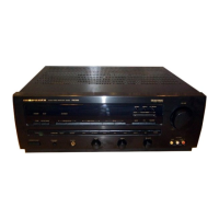
- User-Friendly Controls: The front panel features clearly labeled knobs and push-buttons for source selection, volume, balance, bass, treble, and speaker selection.
- Dial Pointer Lamp and Tuning Meter Lamp: These lamps illuminate the dial and tuning meter, aiding in precise station tuning, especially in low-light conditions.
- Voltage Conversion: The unit can be converted to operate on different power source voltages (e.g., 110V or 220V) by adjusting a voltage selector switch, as illustrated in the manual. This feature requires disconnecting the power supply cord from the AC outlet before conversion.
- FM Muting: A muting push-switch allows users to eliminate inter-station noise during FM tuning.
- Loudness Switch: This feature enhances bass and treble frequencies at low listening levels, compensating for the human ear's reduced sensitivity to these frequencies.
- Stereo LED Indicator: An LED illuminates to indicate when a stereo FM broadcast is being received.
Maintenance Features:
- Original Marantz Parts: The manual emphasizes the importance of using only original Marantz parts for repairs to ensure the product continues to perform to its original specifications.
- National Parts Depot: Marantz maintains a National Parts Depot in California, offering parts availability within 72 hours. Phone orders are encouraged for faster processing, with sales professionals able to quickly determine availability and price information.
- Overseas Parts Ordering: Parts can also be ordered from authorized service facilities in Canada, Australia, Japan, and Europe, ensuring global support.
- Safety Instructions: The manual highlights important safety parts with a triangle symbol, advising users to use only designated parts numbers for these components.
- Alignment Procedures: Detailed alignment procedures are provided for FM (IF, RF, Muting Circuit, Multiplex) and AM (IF, RF) sections, allowing qualified technicians to maintain optimal tuner performance. These procedures involve specific test equipment and adjustment points.
- Voltage Adjustment: A simple DC voltmeter check is outlined to verify the correct voltage reading across specific points, ensuring proper power supply operation.
- Exploded Views and Parts List: Comprehensive exploded diagrams and parts lists are included for the front panel, top cover, rear panel, front chassis, general parts, chassis, and packing materials. These resources are invaluable for identifying and ordering replacement components.
- Schematic Diagrams and Component Locations: Detailed schematic diagrams and component location layouts are provided for all major circuit boards (Tuner Board, Main Amp/Power Supply Board, Volume/Balance Board, Tone Control Board, Pushswitch Board, Headphone Jack Board, Speaker Terminal Board, Speaker Switch Board, Stereo LED Board, Dial Pointer Lamp Board, Tuning Meter Lamp Board). These diagrams are essential for troubleshooting and repair.