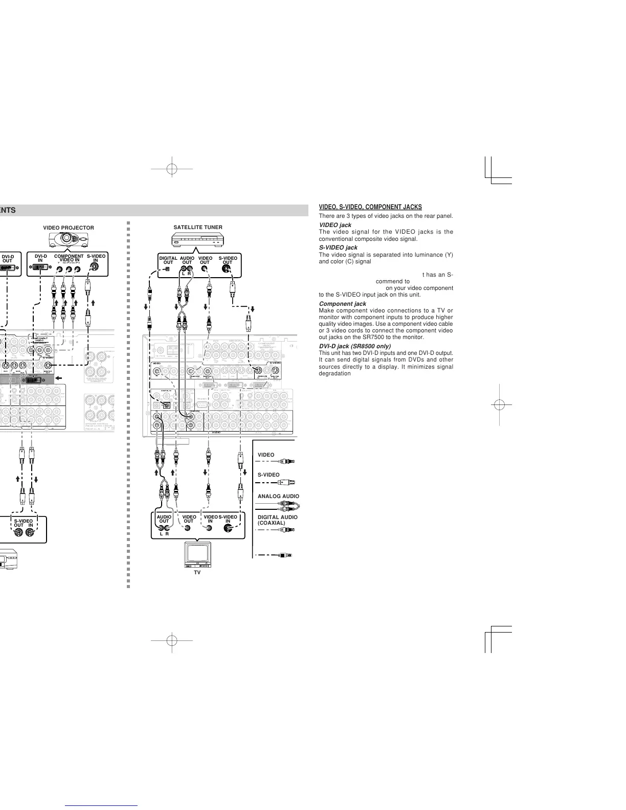
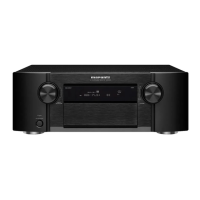
CONNECTING VIDEO COMPONENTS
ANALOG AUDIO
VIDEO
S-VIDEO
DVD PLAYER
VIDEO PROJECTOR
SATELLITE TUNER
DIGITAL AUDIO
(COAXIAL)
VCR
TV
VIDEO, S-VIDEO, COMPONENT JACKS
There are 3 types of video jacks on the rear panel.
VIDEO jack
The video signal for the VIDEO jacks is the
conventional composite video signal.
S-VIDEO jack
The video signal is separated into luminance (Y)
and color (C) signals for the S-VIDEO jack. The S-
VIDEO signals enables high-quality color
reproduction. If your video component has an S-
VIDEO output, we recommend to use it. Connect
the S-VIDEO output jack on your video component
to the S-VIDEO input jack on this unit.
Component jack
Make component video connections to a TV or
monitor with component inputs to produce higher
quality video images. Use a component video cable
or 3 video cords to connect the component video
out jacks on the SR7500 to the monitor.
DVI-D jack (SR8500 only)
This unit has two DVI-D inputs and one DVI-D output.
It can send digital signals from DVDs and other
sources directly to a display. It minimizes signal
degradation caused by analog conversion so that
high quality images can be enjoyed. Select an input
source from the SETUP MAIN MENU. (See page 19.)
Notes:
•
Be sure to connect the left and right audio channels
properly.
Red connectors are for the R (right) channel, and
white connectors are the for L (left) channel.
• Be sure to connect the inputs and outputs of the
video signals properly.
•
If you connect the S-VIDEO or component signal to
the S-VIDEO or component jack on this unit, it is not
necessary to connect the conventional video signal to
the VIDEO (composite) jack. If you use both video
inputs, this unit gives priority to the S-VIDEO signal.
• Each type of video jack works independently.
Signals input to the VIDEO (composite) and S-
VIDEO jacks or component are output to the
corresponding VIDEO (composite) and S-VIDEO
or component jacks, respectively.
•
This unit has the “TV-AUTO ON/OFF” function to
turn the TV ON or OFF automatically, by sensing
the incoming video signal from the VIDEO jacks.
• You may need to setup the digital audio output
format of your DVD player, or other digital source
components. Refer to the instructions of the each
component connected to the digital input jacks.
• There is no Dolby Digital RF input jack. Please
use an external RF demodulator with a Dolby
Digital decoder to connect a video disc player
which has a Dolby Digital RF output jack to the
digital input jack on this unit.
DIGITAL AUDIO
(OPTICAL)
SR8500
only
Note (SR8500 only):
• When a device with DVI
output that supports
HDCP is connected to a
device that does not
support HDCP, signals
are not output. To view
images in DVI, it is
necessary to connect a
display that supports
HDCP.
• There may be no Image
output if connected to a
TV or display that is not
compatible with the above
format.
• Refer to the instruction
manual of the TV or
display to be connected to
this unit for detailed
information regarding the
DVI-D terminal.
*HDCP: High-bandwidth Digital
Content Protection