PIN NO. IN/OUT MARK DESCRIPTION OF TERMINAL
1 INPUT VDD(+4.8V) Power supply terminal
2~3 - Not used in this unit.
4~8 OUTPUT D3~D7 Output terminal for key
9 - Not used in this unit.
10~13 INPUT I1~I4 Input terminal for key
14 INPUT SM IN Signal Meter level IN
15 INPUT TUNED TUNED indicator drive
16 INPUT ST IN Stereo indicator drive
17~20 INPUT AREA OPTION Option terminal for area
/N1 /U1
/F1
17pin L H L
18pin L L L
19pin H L L
20pin L L L
21 - Not used in this unit.
22~23 - GND Ground terminal
24 INPUT VREF Referance power input terminal
25 INPUT VDD Power supply terminal
26 INPUT BACK-UP(CE) Power supply detection
27 - GND Ground terminal
28 INPUT IN Connecting terminal for crystal oscillator.
29 OUTPUT OUT The crystal connected is 32.768KHz.
30 - GND Ground terminal
31 INPUT XIN Connecting terminal for crystal oscillator.
32 OUTPUT XOUT The crystal connected is 8.00MHz.
33 INPUT RESET System reset terminal
34~35 INPUT RMC IN Remote control input terminal
36 INPUT RDS CLOCK Clock input terminal for RDS
37 INPUT RDS DATA Data input terminal for RDS
38 OUTPUT RMC OUT Remote control output terminal
39~43 - Not used in this unit.
44 OUTPUT MUTE Mute Control Output
45 OUTPUT POWER Power on/off signal
46 OUTPUT PDAO Data output terminal for PLL IC(LC72131)
47 OUTPUT PCE Chip enable terminal for PLL IC(LC72131)
48 INPUT PDAI Data input terminal for PLL IC(LC72131)
49 INPUT PCL Clock input terminal for PLL IC(LC72131)
50 INPUT Vfip FIP drive voltage input
51~73 OUTPUT P01~P23 FIP Anode driver outputs.
74 - Not used in this unit.
75~87 OUTPUT G01~G13 FIP Gride driver outputs.
88~90 - Not used in this unit.
91 OUTPUT POWER LED Stand-by LED ON/OFF
92 OUTPUT ANT A ANT A LED ON/OFF
93 OUTPUT ANT B ANT B LED ON/OFF
94 OUTPUT NARROW NARROW LED ON/OFF
95 OUTPUT WIDE WIDE LED ON/OFF
96 - Not used in this unit.
97~100 - GND Ground terminal
19
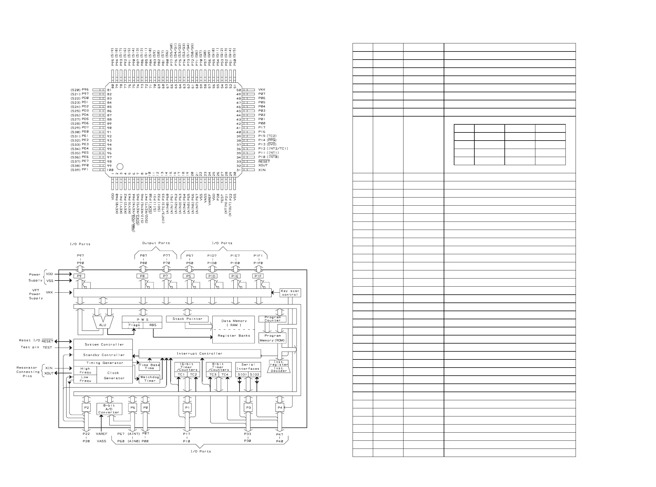
5. MICROPROCESSOR AND IC DATA
IC91 : TMP87PM78F
1. Pin Configuration
2. Block Diagram
20
3. Pin Functions