Band Step Signal Generator Adjust for Adjustment
FM 1 100.10(83.10)MHz 35dB TUNED ON VR11
2 100.10(83.10)MHz 35dB TUNED OFF VR11
MW/LW 1 999(1000)kHz 80dB TUNED ON VR21
(AM) 2 999(1000)kHz 80dB TUNED OFF VR21
Pilot Signal Adjust for Adjustment
ON Different of R and L VR31 (WIDE)
must be maximum VR32 (NARROW)
NO Frequency Adjust for Adjustment
1 100.10(83.10)MHz DC Voltmeter 0V T101
2 100.10(83.10)MHz min T.H.D T102
3 Repeat steps 1 and 2 several times
Modulation Modulation Frequency
MW(AM)/LW 30% 400Hz
FM 40kHz(EUR) 400Hz
75kHz(USA,JPN)
ALIGNMENT INSTRUCTIONS
EQUIPMENT NEEDED
AM Signal Generator Dummy antenna(FM Adjustment)
FM Signal Generator Stereo signal modulator
Oscilloscope Distortion analyzer
VTVM(AC,DC)
Test loop antenna(MW Adjustnent)
IMPORTANT
1.Check power-source voltage.
2.Set the function switch to band aligned.
3.Keep the function input as low as possible to adjust accurately.
4.Modulation and modulation frequency.
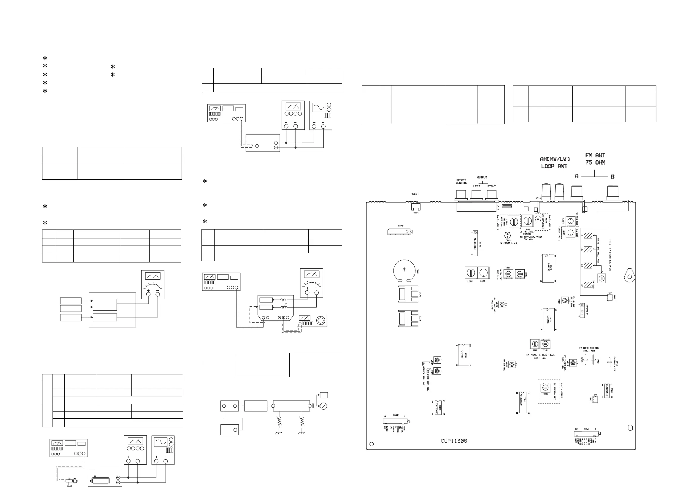
FM, MW/LW TRACKING VOLTAGE ADJUSTMENT
(FM) DC VOLTMETER
CONNECT TO TEST POINT TP11 and GND
(MW/LW) DC VOLTMETER
CONNECT TO TEST POINT TP11 and GND
21
22
NO Band Frequency Adjust for Adjustment
1 FM 87.50(76.00)MHz 1.6V L7
2 MW 522/520kHz 1V L204
3 LW 146kHz 1.3V L205
MW RF ADJUSTMENT
Signal generator : Connects to the MW Ant.
Coil through the loop antenna.
Adjust for the indication of VTVM of the wave form of scope
to be maximum.
FM-RF ADJUSTMENT
Signal generator:Connects to FM ANT.JACK(FM IN)
through the dummy.
NO Step Freq. Adjust for Adjustment
1 612/610kHz Max sensitivity L202(L203),T201,T202
2 1503/1510kHz Max sensitivity CT21
3 Repeat steps 1 and 2 several times.
1 164kHz Max sensitivity L203
2 272kHz Max sensitivity CT22
3 Repeat steps 1 and 2 several times.
MW
(AM)
LW
NO Frequency Adjust for Adjustment
1 90.10(79.10)MHz Max sensitivity L2,L5,L6
2 Repeat step 1 several times
FM MONO DISTORTION ADJUSTMENT
DC VOLTMETER
Connect to TP12(-),TP13(+) through the chock
coil(100uH).
Signal Generator
Connect to FM ANT Jack(FM IN) through the dummy.
Distortion Meter
Connect to the output.
FM/MW(AM) SIGNAL METER LEVEL ADJUSTMENT
FM SIGNAL GENERATOR : Connect to FM ANT Jack(FM
IN) through the dummy
MW SIGNAL GENERATOR : Connect to MW ANT. Coil
thriugh Loop antenna
Band Signal Generator Adjust for Adjustment
FM 100.10(83.10)MHz Sigmal Level:59~61dB VR12
66dB FM(ANT A) IN
MW 999(1000)kHz Signal Level:75~80dB VR22
(AM) 100dB
6. ADJUSTMENT PROCEDURE
FM
AM
GND
GND
TP11
DC EVM
UNIT
MW-SG
MW loop antenna
60cm
kHz
OUTPUT
terminal
AC EVM OSCILLOSCOPE
FM-SG
UNIT
MHz
OUT
OUTPUT
terminal
FM ANT
75ohm
AC EVM OSCILLOSCOPE
FM-SG
MHz
Choke coil
output
DC EVM
UNIT
Chassis
TP12
TP13
DISTORTION
ANALYSER
OUT
100 H
FM-SG Dummy UNIT
FM IN OUTPUT
STEREO
OSCILLOSCOPE
VTVM
VR32VR31
OUT
OUT
STEREO
MODULATOR
EXT
FM STEREO(WIDE/NARROW) SEPARATION
FM/MW(LW) AUTO STOP LEVEL ADJUSTMENT
FM SIGNAL GENERATOR : Connect to FM ANT Jack(FM
IN) through the dummy
MW SIGNAL GENERATOR : Connect to MW ANT. Coil
thriugh Loop antenna
ADJUSTMENT POINT