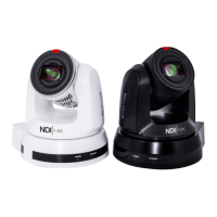
Chapter 3 Function Introduction
3.1 I/O functions Introduction
NO. Item Function Descriptions
1.
Tally indicator light Display the tally light status of the camera
2.
Camera lens 30x HD camera lens
3.
Power LED
Display the status of the camera
4.
Standby LED
Display the status of the camera
5.
RS-232 input
RS-232 input port, at most 7 cameras can be connected in a serial
6.
RS-232 output
RS-232 output port, at most 7 cameras can be connected in a
7.
Kensington lock
Lock hole of safety lock
8.
IR SELECT
The remote control ID setting is only controlled after corresponding
to the Camera Select on the remote control
9.
DC 12 V power
DC power supply connecting port
10.
Ethernet port
Network cable port supports routers or hubs of PoE+ (IEEE
802.3at) with power supply
11.
Audio input Support Line In/Mic In
12.
OUTPUT Switch Adjust the resolution setting. The default is 1080p/59.94
13.
RS-422 Port
RS-422 connecting port, at most 7 cameras can be connected in a
14.
HDMI output HDMI output (Audio output supported)
15.
3G-SDI output
3G-SDI output(Audio output supported)
*Support the audio output of 48 KHz only/resolutions up to 1080p
3.2 Description of LED indicator
Startup in progress
(initialization)
Green light Orange light
3.3 Tally Indicator Light Function Description
3.3.1 The tally indicator light function may be enabled through the control of RS-232
command. The setting method is as follows:
Tally Mode: 8x 01 7E 01 0A 01 0p FF
p = 0: OFF
p = 4: Red light (half-brightness)
p = 5: Red light (full-brightness)
p = 6: Green light (full-brightness)
p = 7: Orange light (full-brightness)
CV630-NDI Manual
www.marshall-usa.com7 8

 Loading...