Doc. No. MV-S105540-00, Rev. A
Page 22 Document Classification: Proprietary Information
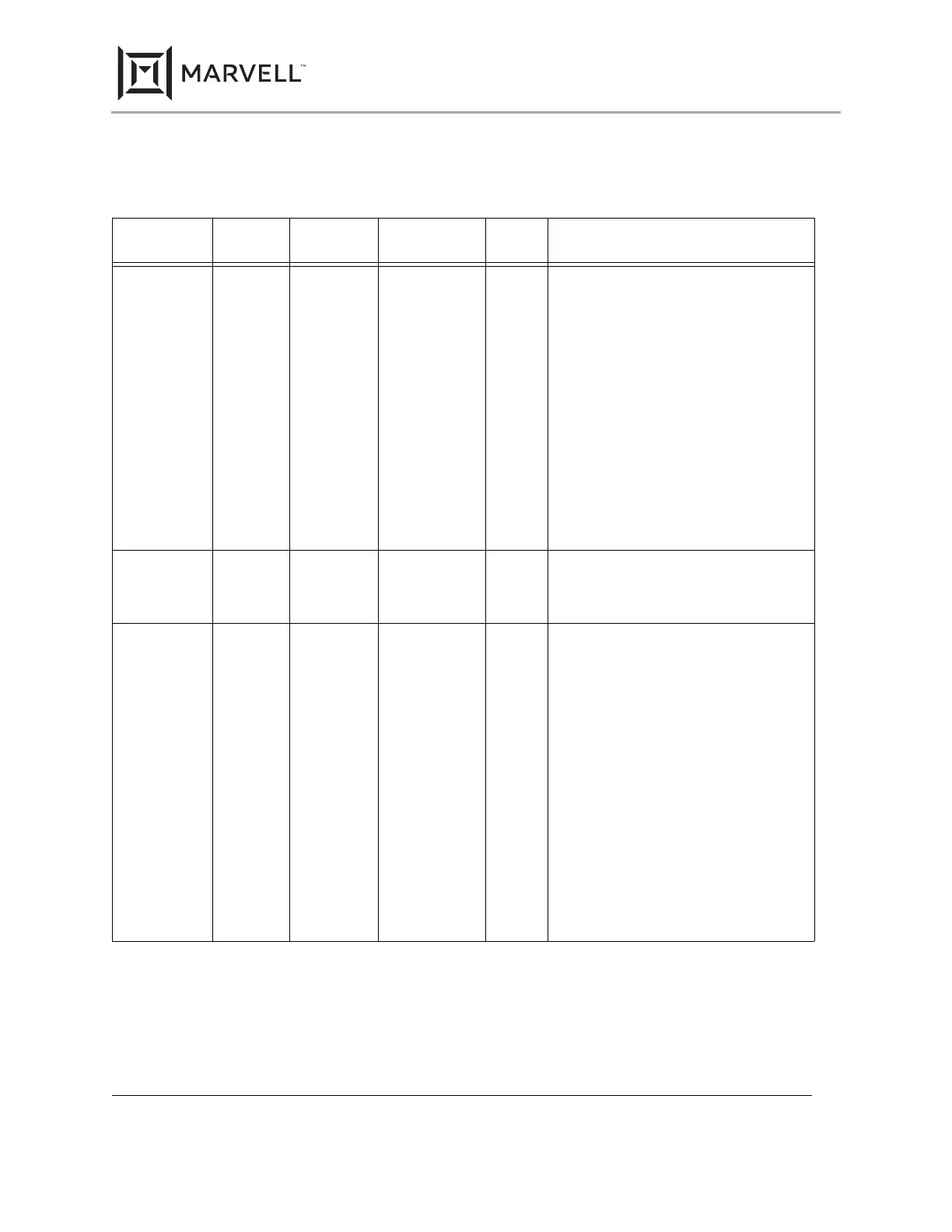
Table 7: 1.25 GHz Serial High Speed Interface
117-TFBGA
Pin #
96-aQFN
Pin #
128-PQFP
Pin #
Pin Name Pin
Type
Description
A3
A4
B38
A44
113
112
S_IN+
S_IN-
I 1.25 GHz input - Positive and Negative.
When this interface is used as a MAC inter-
face, the MAC transmitter’s positive output
connects to the S_IN+. The MAC transmit-
ter’s negative output connects to the S_IN-.
When this interface is used as a fiber inter-
face, the fiber-optic transceiver’s positive
output connects to the S_IN+. The fiber-optic
transceiver’s negative output connects to the
S_IN-.
Input impedance on the S_IN± pins may be
programmed for 50 ohm or 75 ohm imped-
ance by setting register 26.6. The input
impedance default setting is determined by
the 75/50 OHM configuration pin.
A5
A6
A43
B37
110
109
S_CLK+/SD+
S_CLK-/SD-
I Signal Detect input.
For Serial Interface modes the S_CLK± pins
become Signal Detect± (SD±) inputs.
A7
A8
A42
A41
107
105
S_OUT+
S_OUT-
O, Z 1.25 GHz output − Positive and Negative.
When this interface is used as a MAC inter-
face, S_OUT+ connects to the MAC
receiver’s positive input. S_OUT- connects
to the MAC receiver’s negative input.
When this interface is used as a fiber inter-
face, S_OUT+ connects to the fiber-optic
transceiver’s positive input. S_OUT- con-
nects to the fiber-optic transceiver’s negative
input.
Output impedance on the S_OUT± pins may
be programmed for 50 ohm or 75 ohm
impedance by setting register 26.5. Output
amplitude can be adjusted via register
26.2:0. The output impedance default setting
is determined by the 75/50 OHM configura-
tion pin.
88E1111 Product Brief
Integrated 10/100/1000 Ultra Gigabit Ethernet Transceiver
Copyright © 2020 Marvell
December 2, 2020
 Loading...