Doc. No. MV-S105540-00, Rev. A
Page 24 Document Classification: Proprietary Information
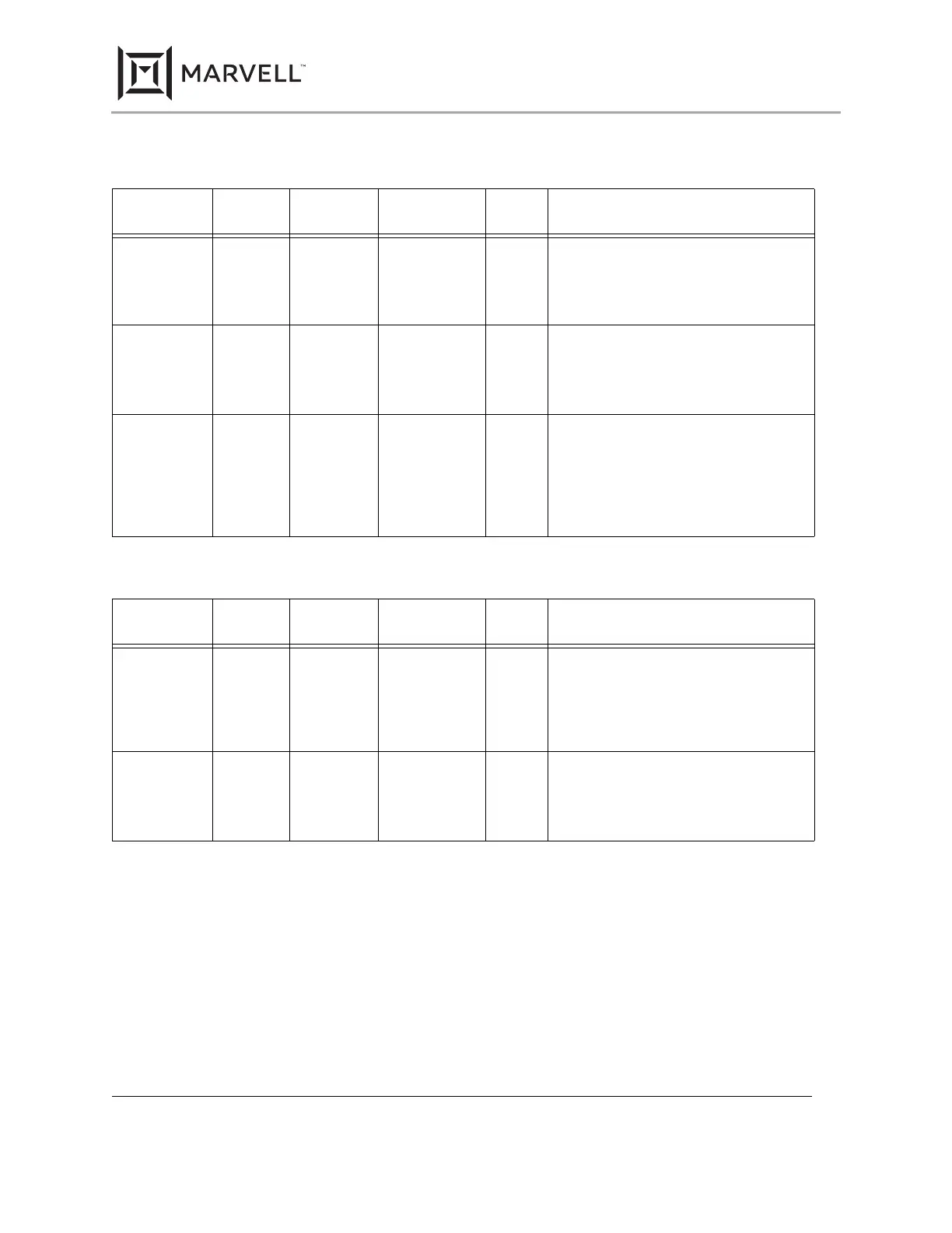
Table 8: Management Interface and Interrupt
117-TFBGA
Pin #
96-aQFN
Pin #
128-PQFP
Pin #
Pin Name Pin
Type
Description
L3 A14 35 MDC I
3.3V
Tolerant
MDC is the management data clock refer-
ence for the serial management interface. A
continuous clock stream is not expected.
The maximum frequency supported is 8.3
MHz.
M1 A13 33 MDIO I/O
3.3V
Tolerant
MDIO is the management data. MDIO
transfers management data in and out of the
device synchronously to MDC. This pin
requires a pull-up resistor in a range from
1.5 kohm to 10 kohm.
L1 A12 32 INTn D The polarity of the INTn pin may be pro-
grammed at hardware reset by setting the
INT_POL bit.
Polarity:
0 = Active High
1 = Active Low
Table 9: Two-Wire Serial Interface
117-TFBGA
Pin #
96-aQFN
Pin #
128-PQFP
Pin #
Pin Name Pin
Type
Description
L3 A14 35 MDC/SCL I Two-Wire Serial Interface (TWSI) serial
clock line. When the 88E1111 device is con-
nected to the bus, MDC connects to the
serial clock line (SCL).
Data is input on the rising edge of SCL, and
output on the falling edge.
M1 A13 33 MDIO/SDA I/O TWSI serial data line. When the 88E1111
device is connected to the bus, MDIO con-
nects to the serial data line (SDA). This pin is
open-drain and may be wire-ORed with any
number of open-drain devices.
88E1111 Product Brief
Integrated 10/100/1000 Ultra Gigabit Ethernet Transceiver
Copyright © 2020 Marvell
December 2, 2020
 Loading...