X-Fly
▲
▲
▲
▲
▲
▲
▲
▲
▲
▲
▲
DISASSEMBLY
GENERAL
– The reference numbers given in this section relate to the components shown in the fork exploded view.
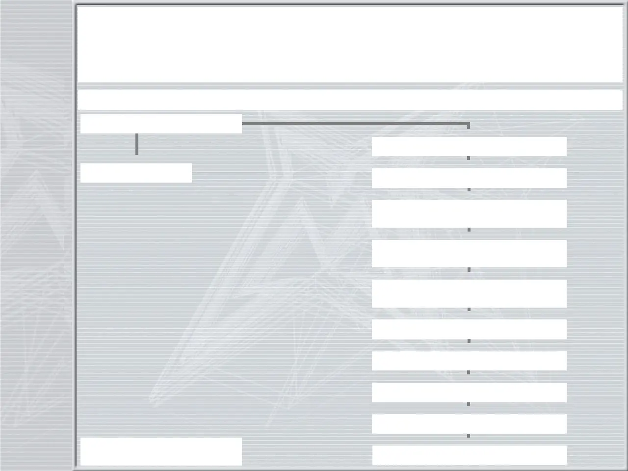
– Before starting any operation. please read the diagram below. It shows the quickest procedure and the exact disassembling sequence.
Locate the part you need to remove in the diagram, then look at the arrows to determine which other parts you need to remove first.
DISASSEMBLY DIAGRAM
FORK OIL CHANGE
STANCHION TUBE CAP FIG. 1/2/3
AIR VALVE CHANGE
FIG. 13
FOOT NUTS FIG. 5
PILOT BUSHING AND
SEAL ASSEMBLY CHANGE
CARWON AND STANCHIONS ASSEMBLY
FIG. 7
DUST SEAL FIG. 8
STOP RING FIG. 9
OIL SEAL FIG. 10
UPPER WASHER FIG. 11
PILOT BUSHING FIG. 12
HYDRAULIC CARTRIDGES,
REBOUND SPRING AND WASHER FIG. 6
HYDRAULIC CARTRIDGES CHANGE
 Loading...