When tightening the gland nuts do not work with long sleeve shirts.
Otherwise it is possible to get caught by the turning shaft and get
injured.
8.1.3. Coupling
As mentioned in Section 6.4, coupling adjustment must be checked
regularly.
Worn out elastic bands must be replaced.
8.1.4. Drive
Apply to the operating instructions of the motor manufacturer.
8.1.5. Auxiliary Components
Check regularly the fittings and the gaskets, replace the worn out pieces
8.2. Service
Our Customer Service Department offers after-sale service. Manager
should employ authorized and trained personnel for
mounting/dismounting procedures. Before these procedures, one must
make sure that pump interior is clean and empty. This criterion is also
valid for the pumps which are sent to our factory or to our service points.
Maintain the safety of the personnel and the environment in every
field procedure.
8.3. Spare Parts
The spare parts of YPSP type pumps are guaranteed for 10 years by
MAS DAF MAKİNA SANAYİ A.Ş.
In your spare parts requests, please indicate the below listed values that
are indicated on your pump’s label.
Pump type and size:
Motor power and speed:
Pump serial number:
Capacity and head:
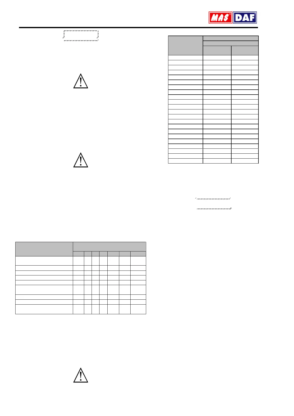
If you wish to keep spare parts in store, depending on the number of
same type of pumps, for two operation years, the quantities which are
listed in the table below are recommended.
The number of equivalent pumps in
the installation
Shaft (Wedge included)
quantity
O-Ring for casting (kit+1)
O-Ring for shaft (if exist) (kit)
Coupling rubber sleeves (kit)
9. NOISE LEVEL AND VIBRATION
The reasons which increase the noise level are indicated below:
Touch of coupling halves due to worn rubber sleeves (incorrectly
aligned)
Noise level increases due to the fact that the pump is not founded
properly (Vibration)
If the installation does not have compensator noise and vibration
increases.
Wearing in ball bearing also increases noise level.
Check if there is any noise increasing elements in your installation.
9.1. Expected Noise Values
Sound Pressure Level (dB) *
(*) Without protective sound hood, measured at a distance of 1 m directly
above the driven pump, in a free space above a sound reflecting surface.
The above values are maximum values. The surface noise pressure level
at dB(A) unit is shown as (L
pA
). This complies with TS EN ISO 20361.
10. DİSASEMBLY, REPAİR AND REASSEMBLY
Before starting work on the pumpset, make sure it is disconnected from
the mains and can not be switched on accidentally.
Follow the safety precaution measures outlined in "safety instructions".
10.1. Disassembly
Close all valves in the suction and discharge lines, and drain the pump
by opening the drain plug (260) and the air plug (261).
Remove coupling guard and other safety guards
Remove all casing main joint nuts (300) dowel pins and bearing
housing (30) connecting bolts.
Separate the casing halves, lifting off the upper half casing (02). This
reveals the pump internals (impeller, wear rings) for inspection
Unscrew the bolts which are connecting the bearing housings (30) to
the bottom half casing (1).
Lift the rotor out of the bottom half casing.
Pull off the pump end coupling half from the shaft (60) using a pull-off
device and remove the coupling key (211).
Remove bearing covers (034) and bearing end covers
Unscrew the shaft nuts (74) Pull the bearing housings (30) and
bearings off the shaft (60).
Pull out stuffing boxes (50) from the shaft.
Remove impeller (25) and sleeves (70-73) by using a suitable device.
Clean all the parts, replace damaged or worn-out ones.
10.2. Reassembly
Reassembly proceeds in reverse sequence to dismantling as described
in section 9.1. You may find the attached drawing useful. The following
points should be noted more particularly:
Never use old o-rings and make sure the new o-rings are the same size
as the old ones.
Before mounting the shaft protecting sleeves (70) inspect the condition
of their rubbing faces. Use new sleeves if the old ones are badly worn,
scored or rough.
Place ball bearings on their places on the shaft by slightly heating or by
using press.
The joint faces of the casing halves are sealed with liquid sealing
compound. The joint faces should be thoroughly cleaned before
reassembly and coated over again with sealing compound. Never use a
paper gasket between the two faces.
 Loading...