After all these processes are accomplished, remove the rubber gasket
from the suction and discharge openings. Open their holes and mount
them again on their intended place.
6.5.3. Specification of work after installation of piping and piping
system
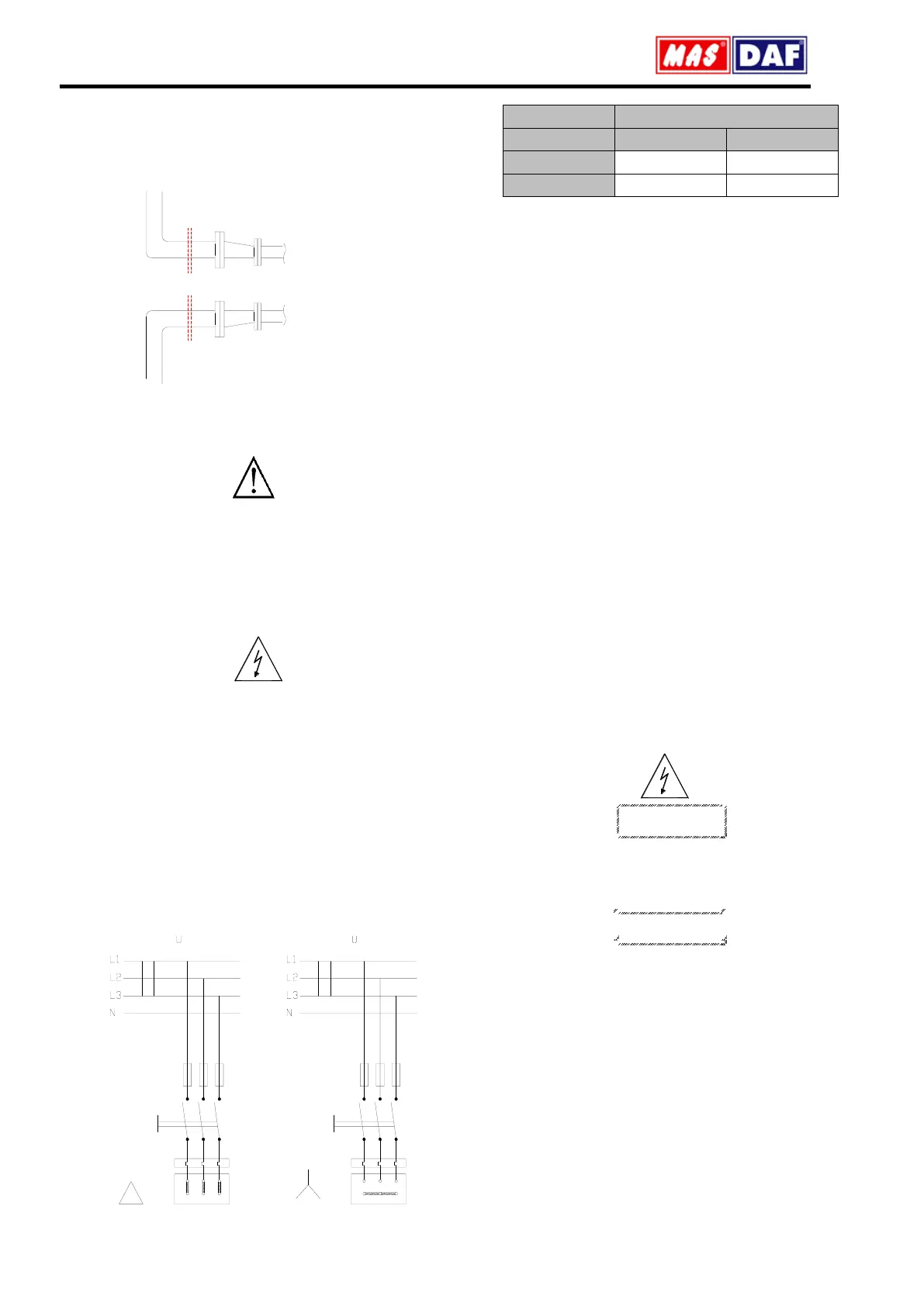
Pump entry
Installing Pipes
lower side entry line
Pump entry
flange
flange
Upper side entry line
Figure 8. Piping system
An illustrative piping system is shown in Figure 10. Appropriate
manometers shall be mounted on suction and discharge pipe lines.
Complete the auxiliary pipe connections in piping system if exist (cooling
to bearing housing, and stuffing box (seal), relief pipe, oil pipe etc.)
6.6. Motor Connection
Motor shall be connected by an electrical technician according to the
connection (switch) diagram. Local electricity policies and current VDE
regulations have to be applied.
Electrical connections have to be made by authorized electricians.
In dismantling the pump, make sure the electricity is cut off before
taking the motor cover out.
Use the appropriate electrical connection to the motor
In environments where there is a risk of explosion, prescribed protective
law and regulations shall be applied by competent authorities.
6.6.1. Motor Connection Diagram
Motors requiring high moments at start up shall not be connected star-
delta
Frequency controlled motors, require high moment at start up and have
to be cooled properly at low speeds. Provide the necessary cooling for
the motors.
W1V1U1
W2 U2 V2
delta
star
U1 V1 W1
W2 U2 V2
Figure 9. Electric Connection Diagram
6.6.2. Motor Protection
Three phased-motor shall be connected to power supply.
Wait the motor to cool down when thermic protected motor breaks in
circuit due to the overheating. Make sure the motor does not start
automatically until it cools completely
In order to protect the motor from overcharging and short circuit use a
thermic or thermic-magnetic relay. Adjust this relay to the nominal
current of the motor.
Electrical equipments, terminals and the components of the control
systems may carry electric current even though they are not
operating. They may cause deadly and serious injuries or
irreparable material damages.
7. COMMISSIONING, START UP AND OPERATING
7.1. Preparations Before Start-Up
Oil Check: Ball bearings are used in YPSP type fire pumps. Long-life, NU
series cylindrical bearings and one row, 63..-C3 series ball bearings are
used respectively on the motor and the shaft sides, balance the axial
force acting on the impeller. Bearings are lubricated with grease.
Check pump seals
Make sure that the pump and the suction pipe is completely filled with
water before the starting. If the pump operates on a positive suction
head, no problem will be encountered. Suction valve is opened and air
drains are un-tightened.
Pumps with foot valve are filled with water by opening the pump filling
tap or, one takes advantage of the water accumulated in the discharge
pipe and by using a small valve the check valve is bypassed and the
pump is filled.
In vacuum pump driven pumps, by operating the vacuum pump one
achieves to fill the pump via increasing the water level in the suction
pipe
Do not start your pump dry
7.2. Checking the Direction of Rotation
The direction of rotation is indicated on the pump label with an arrow.
Apart from special cases, it is clockwise direction when looking from the
motor end. Observe if the pump is rotating in the expected sense by
starting the motor for a very short instant. If it is turning in the opposite
sense, interchange any of two motor leads.
If the motor connection is delta, open the discharge valve slowly.
If the motor connection is star-delta, set the time relay to maximum 30
seconds. Monitor the passage from star to delta by pressing the start
button. As soon as you are assured that the connection is delta, open
the discharge valve slowly. Continue opening the valve until you read
the amperage on the electrical panel
One should always check the labels which show the direction of rotation
and the direction of fluid flow. If you dismount the coupling protection to
monitor the direction of rotation, do not restart the engine before
remounting the protection.
 Loading...