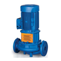
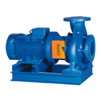
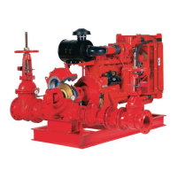
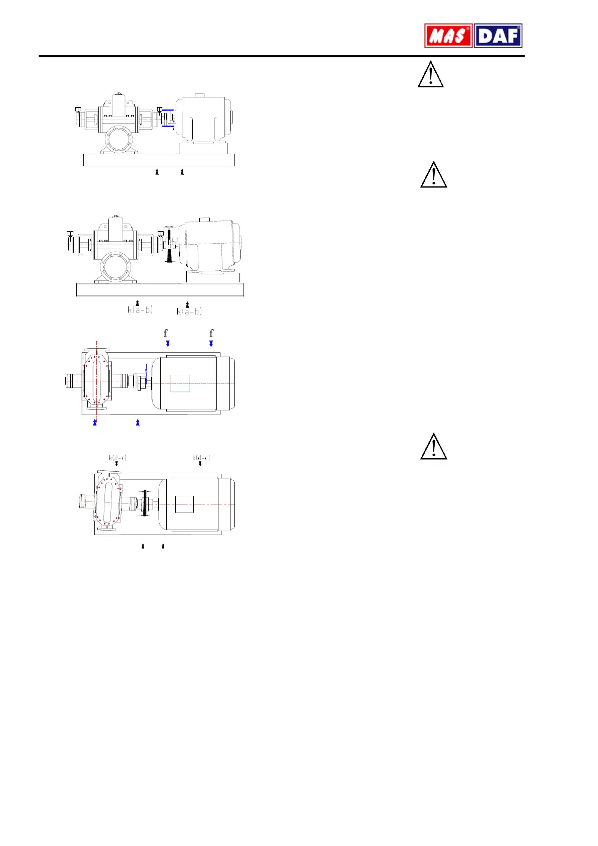
Figures below illustrate the possible coupling misalignments and
the methods to correct them.
Figure 4: Paralel axis misalignment in vertical plane and its correction
Figure 5: Angular misalignment in vertical plane and its correction
Figure 6: Parallel axis misalignment in horizontal plane and its correction
Figure 7. Angular misalignment in horizontal plane and its correction.
6.4.3. Pump and Motor Mounting (Coupling)
If the coupling of the pump group is to be mounted on site, the following
procedure should be followed.
1. Coat the shaft tip of the pump and the motor sides with a sheet of
molybdenum disulfide.
2. Push the coupling halves with a driving apparatus towards the pump
and the motor shafts, until the shaft is fit to snag to the hub of the
coupling. If a driving apparatus is not available, heating coupling halves
(with coupling rubbers off) to an approximately 100
0
C may help the
pushing. It is important that axial force is prevented from occurring while
mounting the coupling. Support pump shaft from the impeller side, and
motor shaft from the fan side while mounting the coupling. If necessary,
dismantle the fan cover.
3. Screw the two bolts in coupling hub.
4. Make sure that a suitable spacing is left between the coupling halves
while mounting pump and the rotor.
5. Horizontal pump groups mounted on the base plate or directly mounted
on the base, alignment of the coupling shall be as described in 6.4.2.
6. Put into place the coupling guard.
According to the accident prevention regulations, all preventions and
protective devices should be in their intended place and in operational
form.
6.5. Piping
6.5.1. General
Do not use the pump as the hinged support for the piping system.
Put enough supports under the piping system in order to carry the
weight of the pipe and fittings.
Avoid piping system loads on pump by installing flexible components
(compensator) to suction and discharge of the pump.
By mounting flexible supporting items, take into consideration the fact
that these items may elongate under the pressure.
Suction pipe shall be in a constantly increasing slope to the pump. Air in
the suction pipe shall be arranged to move into the pump
Discharge piping shall be in a constantly increasing slope to the
reservoir or discharge point, without up and downs which can cause air
pockets in the piping system. At locations where forming of air pockets
is possible, special items like air valve and air cock are mounted to
evacuate the trapped air.
It is important that pipe diameter and fittings are at least as much as the
pump opening diameter or preferable one or two size higher. One
should never use fittings with smaller diameters than the pump exit
diameter. In particular, preferred fittings like foot valve, strainer, filter,
check valves and valves shall have large free passing area, and low
friction loss coefficient.
For piping systems with hot liquids, thermal expansions are to be taken
into account and compensators shall be mounted in accordance with
these expansions. Caution shall be exercised to avoid the loading of
pump in this installation.
6.5.2. Specification of work in piping installation
In installation of pipes, follow the procedures below certainly.
Install the pump on the concrete base as illustrated in Figure 2
Take out the guards (placed by the manufacturer) from suction and
discharge openings of the pump.
Close the suction and discharge flanges with rubber gaskets. This
precaution is important to avoid the undesired substances (weld crust,
weld slag, sand, stone, wood piece etc.) get into the pump. Do not take
off this gasket until the installation is completed.
Start the installation of piping from the pump side. Do the necessary
assembling and welding of the parts in a successive order.
In these operations, do not neglect to put the necessary supports in
their respected locations.
Following above procedure, complete all piping system at suction side
up to the suction tank (or foot valve if available), at discharge side up to
do discharge collector and discharge pipe.
When all installation and welding process is done and the heat
dissipated by welding is removed, dismantle all the bolted connections
from the suction tank to discharge pipe. Take out all demountable parts.
Clean these parts and then paint body coat completely inside and
outside.
Mount the parts again in their intended places. However, this time start
from the discharge line and move downward to the pump. In this
instance, do not forget to check the flange gaskets. If needed, (for
example deformation during welding) replace them.
Concerning the connection of the pump flanges to piping, in case of
misalignment of axis and flange holes, do not force the system to
eliminate the misalignment. Forcing the system may cause difficult-to-
correct problems.
If there is an axial misalignment between the flanges of the pump and
the pipe, due to the welding or any other reasons, cut the pipe from a
suitable location in order to fix the problem. Connect the pipe (pump
side) to the pump. After carrying out the necessary correction, connect
the parts again by welding.
Dismantle and clean the last welded part. Repaint again and mount on
its place.
 Loading...