4.1.4. Shaft
The shaft is longer for standard YPSP type pumps which have soft
packing applications.
4.1.5. Bearing and Lubrication
Rolling bearings are used in YPSP type pumps. They support radial load
caused by the impeller. A NU series cylindrical bearing at the motor side
of the pump and a 63-C3 series ball bearing on the other side of the shaft
are used. They are all long life rolling bearings. Rolling bearings are
lubricated with grease.
Since the impeller is double suction type, the axial force balances
automatically. To prevent the leakage flow into bearing housing, there are
deflectors in front of the bearing covers.
4.1.6. Seals
In YPSP type pumps gland squeezed, teflon knit soft packing are used.
There is a lantern ring in the stuffing box.
Non-cooled packing is standard. (It is acceptable up to 90
o
C )
(See The Fig. 11 : Design with soft packing)
4.2. Construction Of Pump Group
4.2.1. Drive
A hermetic, 3 phase, fan cooled, squirrel caged,in according to DIN
42673-IM 1001B3 type electrical motor which complies with DIN IEC and
VDE is used to drive the pump in proper speed and power.
Specifications of electrical motor
Isolation class : F
Protection class : IP 54-IP 55
Frequency : 50 Hz.
Running type : S1
Start up type : 3x380 V(Y) up to 4 kW
More than 4 kW, 3x380(Δ) + (Y/ Δ)
There is another possible application to drive the pump with a diesel
engine.
4.2.2. Coupling and coupling cover
A flexible shaft coupling with or without secondary component in
accordance with DIN 740 is used. A coupling cover is given in
accordance with EN 294 in case of the pump group includes the coupling
and chassis.
Pump can only be run with a coupling guard in
accordance with EN 294according to safety instructions.
If there is no coupling cover, it is provided by the operator.
4.2.3. Base plate
It is manufactured from U profile steel in accordance with DIN 24259
5. TRANSPORT AND STORAGE
Suction, discharge and all auxiliary fittings must be closed during
transport and storage. Dead-end covers must be removed while the pump
unit is being installed.
5.1. Transport
Pump and pump group must be carried safely to the installation location
by lifting equipments.
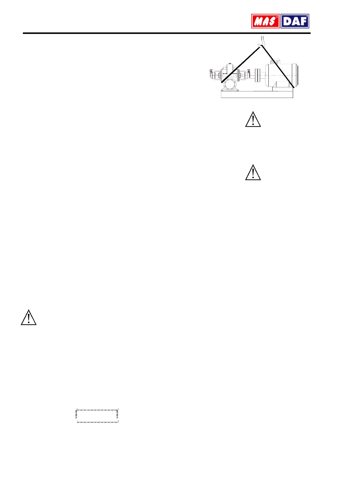
Current general lifting safety instructions must be applied. Please use a
suspension system shown in figure while you are carrying and lifting the
pump unit. The suspension rings may be broken because of the
excessive load and may result in a damage of the pump. Prefer fabric
cable for suspension
Fig.1: Transport of pump group
Incorrect lifting may damage the pump unit and cause injuries
Damages caused in transport.
Check the pump when it is delivered to you. Please let us know of there is
any damage.
5.2. Storage
Please keep the unit clean and dry area during storage.
If the pump is out of use for a long time, please consider the instructions
below:
1. If there is water inside the pump, drain it.
2. Clean the pump casing and impeller by jetting clean water for a short
time.
3. Empty water inside the pump casing, suction line and discharge line.
4. Add small amount of antifreeze inside the pump casing if it is not
possible to empty it completely. Rotate the pump shaft by hand to mix
the antifreeze.
5. Close the suction and discharge exits with gasket
6. Spray an anti-corrosive into the pump casing.
7. Rotate the pump shaft by hand once in every month, in order to protect
it from freezing and to lubricate the bearings
6. ASSEMBLY / INSTALLATİON
6.1. Installation
In our standard production, the pump and the motor have been installed
in a common base plate.
6.1.1. Location of Installation
Pump shall be installed in a location where the control and the
maintenance of the pump are easily made. The pump room shall be
suitable for operation of lifting systems such as freight elevator, forklift,
etc.
The pump group should be installed in the lowest possible location of the
pumping system in order to achieve the highest suction pressure.
6.1.2. Location of Installation- Local Ambient Temperature
When the local ambient room temperature exceeds +40
0
C in a pumping
system, suitable ventilation should be provided in order to remove the
heat dissipated to the environment and supply fresh air.
6.2. Type of Connection
Type of connection depends on the design type and the size of the pump
and the motor, as well as the local installation conditions. Foot-mounted
horizontal pump-motor units have been installed in a common base plate.
6.3. Foundation
6.3.1. General
Base plate of the pump must be grouted. The foundation shall be of
concrete or steel framework.
NOTE: The foundation shall distribute the weight of the pumping group
evenly.
 Loading...