GENERATORS
Dans la liaison en sèrie on peut pr_lever simultanèment
la puissance à une tension de 110 (120) V entre les points
F1-F2 et P1-P2 qu'à une tension de 220 (240) V entre les
points P1 et F2, selon le schèma de la figure 22.
- S'assurer que la somme des charges à alimenter ne
soit pas supèrieure à la puissance nominale du groupe
èlectrogène.
- Nous recommandons de placer, entre le gènèrateur et
les applications èlectriques, des protections
magnètothermiques ou similaires, selon les tableaux
que nous reportons ci-après.
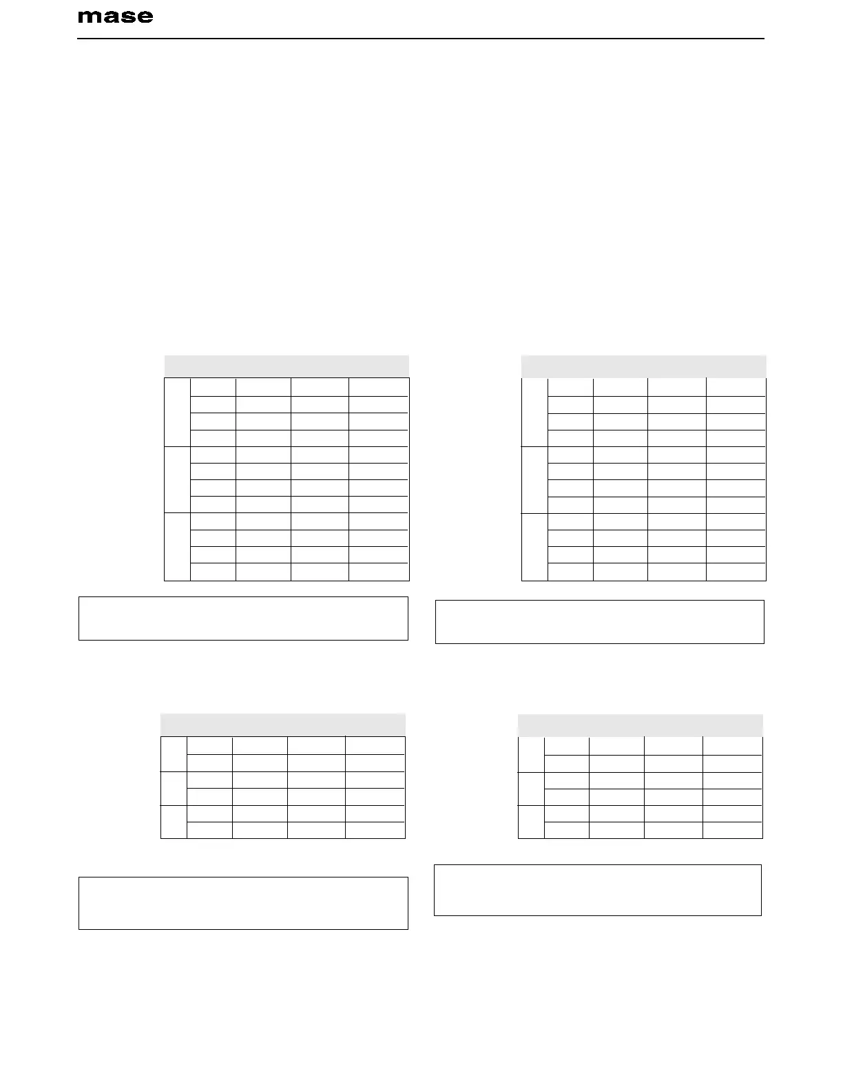
Distribution à tension unique
Hz V W A
50 110 3500 31.8
60 120 4000 33.3
50 220 3500 15.9
60 240 4000 16.7
50 110 6500 59.1
60 120 7300 60.8
50 220 6500 29.5
60 240 7300 30.4
50 110 9200 83.6
60 120 10000 83.3
50 220 9200 41.8
60 240 10000 41.7
IS 3.8/4.5
IS 7/8
IS 10/11.5
TAB 1
Hz V W A
50 110/120 3500 15.9
60 120/240 4000 16.7
50 110/220 6500 29.5
60 120/240 7300 30.4
50 110/220 9200 41.8
60 120/240 10000 41.7
IS 3.8/
4.5
IS 7/8
IS 10/
11.5
TAB 2
Hz V W A
50 110 3500 31.8
60 120 4000 33.3
50 220 3500 15.9
60 240 4000 16.7
50 110 6500 59.1
60 120 7300 60.8
50 220 6500 29.5
60 240 7300 30.4
50 110 9200 83.6
60 120 10000 83.3
50 220 9200 41.8
60 240 10000 41.7
IS 3.8/4.5
IS 7/8
IS 10/11.5
TAB 1
Hz V W A
50 110/120 3500 15.9
60 120/240 4000 16.7
50 110/220 6500 29.5
60 120/240 7300 30.4
50 110/220 9200 41.8
60 120/240 10000 41.7
IS 3.8/
4.5
IS 7/8
IS 10/
11.5
TAB 2
NOTE: Un seul magnètothermique doit ètre installè dans ce cas
(se reporter à la figure 20/21).
Distribution à tension double
NOTE: deux magnètothermiques doivent ètre installès dans ces
cas (se reporter à la figure 22), dimensionnès sur les valeurs du
courant (A) reprises sur le tableau 2.
4.4. Commutation gènèrateur - rèseau
Il faut interposer sur la ligne d'utilisation un commutateur
qui permette de commuter les applications du gènèrateur
à une ligne d'alimentation externe. Le commutateur doit
ètre dimensionnè sur la base de l'entitè des charges en
jeu; un schèma d'ensemble est fourni par la figure 23.
In serial connection, power can be picked up both at 110
(120) V between points F
1
- F
2
and P
1
- P
2
and at 220 (240)
V between points P
1
and F
2
at the same time, as shown
in the diagram in fig. 22.
- Ensure that the sum of the loads to be supplied does not
exceed the nominal power of the electric generator.
- Magnetothermic protective devices or similar should be
placed between the generator and electrical equipment,
according to the tables shown below.
Single voltage distribution
N.B: In these cases two magnetothermic devices should be
installed, see fig. 22, dimensioned on the current values (A)
shown in Table. 2.
4.4. Generator - Mains switching
A switch should be placed on the line to switch the user
appliances from the generator to an external power line.
The switch should be dimensioned according to the size
of the loads: a general diagram is shown in fig. 23.
N.B: In these cases just one magnetothermic device should be
installed, see fig. 20/21.
Double voltage distribution