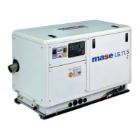
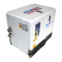
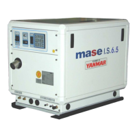
GENERATORS
THE GUARANTEE OF THE PRODUCT BECOMES
VOID IF THE SPECIFICATIONS CONTAINED IN THE
FOLLOWING INSTALLATION MANUAL ARE NOT
RESPECTED
LE NON-RESPECT DES DIRECTIVES REPRISES
DANS CE MANUEL D'INSTALLATION ENTRINE
LA DECHEANCE DE LA GARANTIE SUR
LE PRODUIT
E
1.1 Characteristics of the installation space ............. 5
1.2 Fastening the unit to the ground ......................... 5
1.3 Ventilation ..........................................................5
2.1. Sea water feed system ...................................... 5
2.2 Typical installation with electric generator
above the water-line ............................................9
2.3. Typical installation with electric generator
below the water-line ............................................9
2.4. Typical installation of electric generator
with "E/G" separator above and below
the water-line ................................................... 11
2.5. Components .................................................... 13
2.6. Drainage system .............................................. 15
3.0 Fuel circuit ....................................................... 15
4.1. Battery connection ........................................... 17
4.2. Control panel connection .................................. 17
4.3. A.C. Connection ............................................... 19
4.4. Generator - Mains Switching ............................ 21
INSTALLATION1
2
COOLING WATER CIRCUIT
INSTALLATION
2
E
1.1 Caracteristiques du local .................................... 5
1.2 Ancrage du groupe ............................................. 5
1.3 Ventilation ..........................................................5
2.1. Système d'amenèe d'eau de mer ....................... 5
2.2 Installation typique avec groupe èlectrogène
au dessus de la ligne de flottaison .....................9
2.3. Installation typique avec groupe èlectrogène
sous la ligne de flottaison ................................... 9
2.4. Installation typique de groupe èlectrogène
avec pot separatrice eau/gas dèscharge au
dessus et sous de la ligne de flottaison............ 11
2.5. Composants .................................................... 13
2.6. Système de purge ............................................ 15
3.0 Circuit du combustible ..................................... 15
4.1. Branchement de la batterie .............................. 17
4.2. Branchement du tableau de commande ........... 17
4.3. Raccordement c.a. ........................................... 19
4.4. Commutation gènèrateur-rèseau ...................... 21
CIRCUIT D'EAU DE REFROIDISSEMENT
1
INDICE
3
FUEL CIRCUIT
3 CIRCUIT DU COMBUSTIBLE
CONNEXIONS ELECTRIQUES4ELECTRICAL CONNECTION4