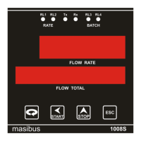
Flow Indicator Totaliser 1008S
REF NO: m18A/om/101
Issue No: 17
10. COMMUNICATION GUIDELINES
10.1 Introduction
The unit can be connected in RS-485 communication data link either in multi drop or repeat
mode. Each unit must have unique Serial Number. Entire range of addresses (1 to 247) may
be used. Before starting any communication, choose a baud rate compatible to the host
computer. The serial protocol used is MODBUS RTU.
10.2 Function Code for Modbus
Use to read Relay and Digital output status
Use to read PV, Control, RSP output etc
Use to write digital parameter value.
Use to write programmable register
The error checking field contains a 16-bit value implemented as two eight-bit
bytes. The error check value is the result of a Cyclical Redundancy Check (CRC)
calculation performed on the message contents.
Note:
For Analog Read:
FLx (FL1, FL2, FL3, FL4, and FL5) consists of 9 selectable values from 10 to 100.
For 10 it will read…. 0
For 20 it will read…. 1
If FL1 =100, Hex address 0x0024 will show 9.
For Digital Read/Write: Cmd Action = 1;
Reg. Address = 0x0001 to 0x0004.
1. Relays will read 0- OFF (relay) 1 – ON
2. For start /stop function
Cmd Action = 5
Reg Address = 0x0005
For Start – write 1
For Stop – write 0
10.3 Modbus RTU protocol addresses for RS 485 Communication
10.3.1 Addresses Of 1008S Standard
R/W (0 for Normal, 1 for Counter)


 To Next Page