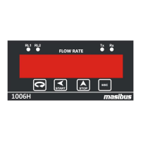
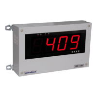
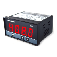
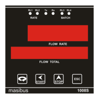
Flow Indicator Totaliser 1008S
REF NO: m18A/om/101
Issue No: 17
3. SPECIFICATIONS
3.1 Measured input signal
1(one) with Optional 2 & 3
± 0.025% of full scale ± 1 Count
Available for 1 to 5VDC, 4 to 20 mA, 0 to 10 KHz.
250 Ohms Internal for current Input
320K Ohms for Voltage Input
ALLOWABE SIGNAL
SOURCE RESISTANCE
DC input voltage: 1KΩ or less . Effect from allowable signal
source Resistance: 0.031 % / 100Ω or less
Common Mode: > 100db
Normal mode: > 40db
Input to relay o/p: < 1 second.
Input to Analog o/p: < 1 second or less, 63 % ( 10 - 90%)
(Time required for o/p to reach 63% of the maximum
excursion when PV changes from 10% to 90%)
Note:
Input type is factory set.
* Max. Pulse level<=24V , Min. pulse level > 1.0V
** ±(0.45% of Reading + 1 Digit)
3.2 Loop Power Supply Specification
3.3 Retransmission Output
0.25% of full scale +1 count
3.4 Contact Input (Digital input)
Input 1 : Stop Batch
Input 2 : Integration total zero(Therefore Batch total and roll
count will be zero)
Input 3 : Start Batch
Input 4 : Batch total zero


 To Next Page