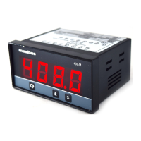
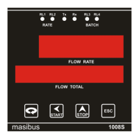
Flow Indicator Totaliser 1008S
REF NO: m18A/om/101
Issue No: 17
Non- voltage contact input or transistor open collector input
12VDC,10mA or more (for non – voltage contact input)
For non-voltage contact input
ON = contact resistance of 1KΩ or less,
OFF = contact resistance of 20KΩ or more
For transistor contact input
ON = 2V or less
OFF = leak current of 100µA or less
MINIMUM RETENTION
TIME FOR STATUS
DETECTION
NUMBER OF RELAY CONTACT
OUTPUTS
4 (2 Flow alarm relays, 2 Batch relays)
3.6 Display Unit Specification
0.56” 5 digit 7- segment red display
0.40” 8 digit 7- segment red display
Same integrated total display
3.7 Electrical Specification
85 to 265 VAC, 50Hz ; 24VDC(optional)
Between primary terminal and secodary terminal :
1500VAC(For 1 min)
Between primary terminal and ground terminal : 500VDC(for
1 min)
Between ground terminal and Secondary terminal : 500V AC
(for 1 minute).
(Primary terminal: Power supply, relay output)
(Secondary terminal: Analog input/output signal terminals,
contact input terminal)
3.8 Isolation specification
Between power supply terminal and ground terminal: 500
VDC, 50MΩ
Isolated from other input/output terminals. Not isolated from
24Vdc supply (Transmitter power supply) and internal circuit.
24V DC SUPPLY FOR
TRANSMITTER
Not isolated from the measured input terminal & internal
circuit, isolated from other input/output terminals.
RETRANSMISSION
OUTPUT TERMINAL
Isolated from other input/output terminals and internal circuit.
Isolated from other input/output terminals and internal circuit.
Isolated from other input /output terminals and internal


 To Next Page