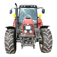
Massey Ferguson 6400 - Issue 1
02C01.11
Splitting - GBA20 gearbox / Centre housing
Special point (Fig. 12)
On tractors fitted with creeper gears:
- Remove screw (1).
- Pull the pin (2) outwards in order to free the “D”
finger of the fork.
53. Mark then disconnect:
- the electrical connectors on the selector cover,
the control unit (Dynashift – reverse shuttle) and
the right-hand hydraulic cover
Servicing on the left-hand side of the
tractor
Mark then disconnect:
- the harness of the fuel gauge on the tank
- the gas oil feed and return hoses on the engine
(block ports immediately)
- the vent hose on the tank
54. Drain the tank (if necessary) and remove it.
55. Disconnect the transmission lubricating pipe or
hose located at the front left-hand side of the
gearbox.
Servicing under the cab
56. Mark then disconnect:
- the right- and left-hand brake cables (block ports
immediately)
- the steering hose of the trailer brake valve, if
fitted (block ports immediately)
- the handbrake cable
- the speed sensor connectors (PTO and ground
speed).
Servicing at the rear of the tractor
57. Mark and disconnect cables:
- of the auxiliary spool valves (optional)
- of the power take-off (all versions)
58. Mark and disconnect the connectors:
- on the electrohydraulic spool valves
- on the lift control valve
- on the power take-off
- on the effort sensors
Preparing for disassembling
59. Cancel the front axle oscillation (all versions) by
sliding a suitable chock in either side of the support
(1) (Fig. 13).
60. Chock the front wheels.
61. Position a fixed stand at the back of the gearbox
(Fig. 15).
62. Position a mobile stand at the front of the centre
housing and another at the back (Fig. 15).
63. Separate the cab from the supports on the rear
right- and left-hand sides (fixed or suspended cab
versions – see chapter 12).
64. Using two straps with hooks, gently lift the cab
with the rear pillars (Fig. 15).
65. Fit a wooden chock temporarily between the cab
and the pillars.
Fig. 12
Fig. 13

 Loading...


