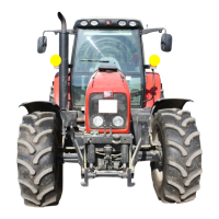
Massey Ferguson 6400 - Issue 4.a
2A30.7
Splitting the front frame/Sisu engine - MF 6497-6499
Disassembly
The lower screws M20x135 (2) and M24x165 (3),
attaching the front frame to the lower engine housing,
are not accessible on 4 WD tractors (Fig. 10). These
screws are facing the drive pinion carrier, which also
serves as a steering ram support.
Front frame / engine splitting takes place in two steps:
- first step: removing the front axle (fixed or
suspended);
- second step: splitting the front frame (radia-
tors/cooler) from the engine
First step: removing the front axle (fixed or
suspended, see chapter 8)
23. Cancel the front axle oscillation (all versions) by
sliding a suitable chock in at each side of the frame
and front axle (1) (Fig. 11).
24. Chock the rear wheels.
25. Remove the front wheels.
26. Install (Fig. 12):
- a fixed stand at the front of and under the
gearbox;
- a fixed stand under the engine.
3
2
MA-02-05118A
Fig. 10
1
MA-02-05119A
Fig. 11
MA-02-05120A
Fig. 12

 Loading...


