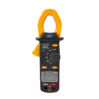
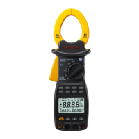
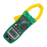
RESISTANCE MEASUREMENT
1.
Connect the red test lead to “Ω ” jack and black test lead
to the “COM” jack (The polarity of red lead is positive “+”).
Set the rotary switch at desired ”Ω” range position.
Connect test leads across the resistor to be measured and
read LCD display.
If the resistance being measured is connected to a circuit
,
turn off power and discharge all capacitors before applying
test probes.
NOTE:
1.
If the resistance being measured exceeds the maximum
value of the range selected or the input is not connected, an
overrange indication
“
1
”
will be displayed.
When checking in-circuit resistance, be sure the circuit under
test has all power removed and that all capacitors have been
discharged fully.
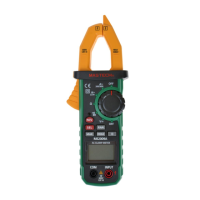
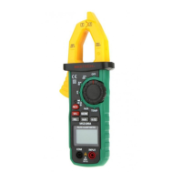
AUDIBLE CONTINUITY TEST
1.
Connect red test lead to “Ω ” jack, black test lead to
“COM” jack.
Set range switch to “ ” position.
Connect test leads to two points of circuit to be tested. If
continuity exists, built-in buzzer will sound.
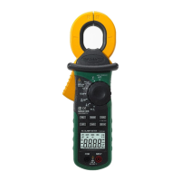
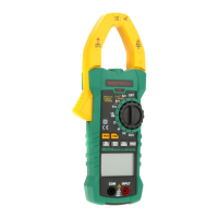
DIODE TEST
1.
Connect the red test lead to “Ω ” jack and the black test
lead to the “COM” jack (The polarity of red lead is positive
“+”.).
-7-