07
08
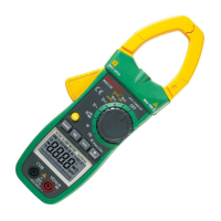
AC Current Measurement
1. Place function measuring range switch to AC
current measuring range.
2. Press the trigger, open clamp head, clip the lead
in the clamp to measure the lead current. Note:
Clamping two or more leads at the same time will
give invalid reading.
3. Read the measuring result from display.
Notes!
∆ If the range of current to be tested is not known in
advance, please place function measuring switch
to the maximum current range, then gradually
reduce to obtain the correct range.
Resistance Measurement
1. Insert red probe and black probe to “INPUT” and
“COM” jack.
2. Place function measuring range switch to required
Ω position, and connect the probe to resistor to
be tested.
3. Read the measuring result from display.
Note:
∆ If measured resistance value is more than the
maximum value of chosen measuring range, it will
show will “OL`”. At this time, select a higher range.
∆ When checking online resistance, first turn off all
power supplies in the circuit to be measured and
discharge all capacitors fully.
∆ When measuring the resistance more than 1MΩ,
the reading will be stable after several seconds.
This is normal for high resistance measuring.
Diode Test
Insert red probe to “INPUT” and insert black probe to
“COM” jack. At this time, red probe polarity is “+”.
Place function measuring switch to position. Red
probe is connected to the anode of diode under
measurement, and black probe is connected to the
cathode of diode under measurement. Read
approximate forward voltage drop value from the display.
Circuit Continuity Test
Insert red probe to “INPUT” jack, and insert black
probe to “COM” jack. Place function measuring switch
to position and press SEL key to enter circuit
continuity test. Probe is connected to two points of
circuit under measurement. In continuity test, when
test resistance is less than 50Ω, buzzer will sound.
When it is from 50Ω to 90Ω, buzzer may or may not
sound. When it is more than 90Ω, buzzer won't sound.
Non-Contact Voltage Detection
Press NCV key. Place non-contact sensor close to the
conductor. When test voltage is greater than 90V AC
(RMS) and when the meter is close to the conductor,
the meter induction voltage indicator will flash and
buzzer will sound.
Note:
1: Even there is no indication, voltage may exist. Don't
use non-contact voltage detector to judge whether
there is voltage in the wire. Detection operation
could be affected by socket design, insulation
thickness, type and other factors.
MULTIFUNCTION DIGITAL MULTIFUNCTION DIGITAL