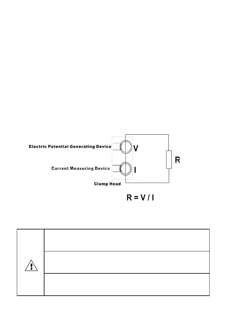
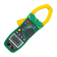
clamp-type grounding resistance meter is to measure the loop
resistance. See below. The jaw section of the clamp meter
consists of a voltage coil and a current coil. The voltage coil
provides the excitation signal and induces a potential V on the
circuit under test. Under the action of the potential V, a current
I will be generated in the circuit under test. The clamp meter
measures V and I and uses the following formula to obtain the
measured resistance R.
R=V/I
IX. Operation Method
1. Boot up
Boot , DO NOT press the trigger, don’t open jaws,
nor clamp any wire
Boot complete, show “OL Ω”, then press the trigger,
open jaws, clamp the measured wire
Before booting up, the trigger should be pressed for
a couple of times to ensure the jaws are well closed.