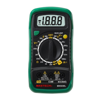
2.5 INPUT JACKS
The unit has four input jacks that are protect against
overload to the limits. During use, connect the black test
lead to the COM jack and the red test lead as shown
below:
Function
Ω V/Ω/Hz 250V dc or rms ac
V/Ω/Hz 250V dc or rms ac
V/Ω/Hz 250V dc or rms ac
μA/mA mA 500mA dc or rms ac
A A 10A dc or rms ac
μA/mA and A ranges are protected by fuses.
3. OPERATING INSTRUCTION
3.1 MEASURING VOLTAGE
1. Connect the black test lead to the COM jack and the
red test lead to the V/Ω jack.
2. Set the rotary switch at the desired V or V ~
range position and connect test leads across the
source or load under measurement.
3. Read LCD display. The polarity of the red connection
will be indicated when making a dc voltage
measurement.
3.2 MEASURING CURRENT
1. Connect the black test lead to the COM jack and the
read test lead to the mA jack for a maximum of 500mA.
- 6 -