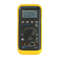
For a maximum of 10A, move the red lead to the A jack.
2. Set the function switch at μA, mA or A range to be
used and push “SELECT” button to select DCA or ACA
measuring mode.
3. Connect test leads in series with the load under
measurement.
4. Read LCD display. The polarity of the red lead
connection will be indicated when making a DC
measurement.
3.3 MEASURING RESISTANCE
1. Connect the black test lead to the COM jack and the
red test lead to the V/Ω/Hz jack. (NOTE: The polarity of
red lead connection is positive “+”)
2. Set the rotary switch at Ω position and connect test
leads across the resistance under measurement. Read
LCD display.
NOTE:
1. For resistance above 1MΩ, the meter may take a few
seconds to stabilize reading.
2. When the input is not connected, i.e. at open circuit,
the figure “OL” will be displayed for the overrange
condition.
3. When checking in - circuit resistance, be sure the
circuit under test has all power removed and all
capacitors are full discharged.
3.4 MEASURING FREQUENCY
1. Connect the black test leads to the COM jack and the
- 7 -

 Loading...