19
SUCTION LINE
TEMP SENSOR
FAN DELAY
PRESSURE
TRANSDUCER
DEFROST TERMINATION
TEMP SENSOR
6" TO 10"
EVAP OUT
Temperature Sensors
The application range of the temperature sensors used for this controller is -60
o
F to +150
o
F. If the sensor
detects a temperature out of the range, an alarm will show on the controller display.
Three temperature sensors are used in the Master Controller 2.0 refrigeration system. They are the room
temperature return air sensor, the evaporator defrost termination temperature surface sensor and the
evaporator outlet (suction line) temperature surface sensor. All sensors
are solid state devices with the same characteristics that change electrical resistance in response to a change
in temperature.
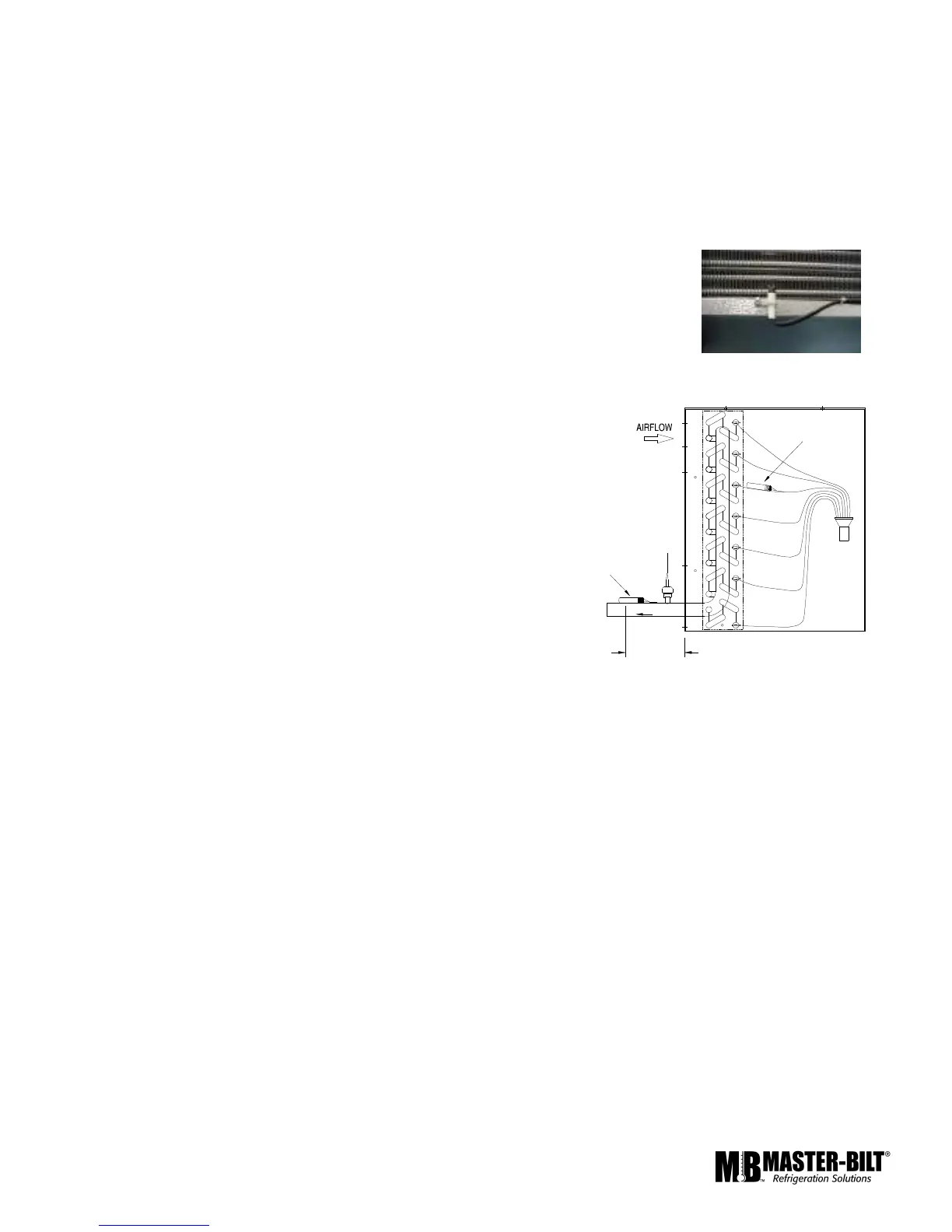
The room temperature sensor is factory-mounted on the lower back of the
evaporator at the drain pan. This placement avoids heat from defrost heaters
and lights and still allows a good air stream over the sensor. Figure 3 shows a
typical mounting of the room temperature sensor.
The defrost termination sensor is mounted on one of the distributor tubes close
the coil end plate. The outlet sensor is mounted on the suction line at the outlet
of the evaporator as shown in Figure 4. These sensors are interchangeable.
SENSOR SERVICE INSTRUCTIONS
Care must be taken when brazing the suction line at the
evaporator. The outlet sensor must be taken out before brazing.
After brazing, fasten the sensor with the metal strap provided.
Make sure the sensor is tight and has good contact with the
suction line.
The temperature sensor cannot be repaired. Using the
measurements in Chart A below, you can determine if they are
functioning correctly. If the sensors are found out of tolerance,
they should be replaced.
As mentioned above, the temperature sensor changes
electrical resistance in response to temperature changes.
Disconnect the sensor from the controller, check the temperature
at the sensor location, then check and record the resistance
through the temperature sensor.
Procedures to check temperature sensor tolerance with ice water:
1. Use a cup of water with well-stirred ice. The water temperature should be an even 32°F.
2. Submerge the room temperature sensor (TS2) into the water while the Master Controller 2.0 is
normally operating. Check the display for the value. If the sensor shows 32°F, it is working properly.
3. Press the right or left buttons until the display shows the name of one of the variables. Press the up or
down buttons until the display reads ‘TCOI’, the defrost termination sensor (TS3). Press the ‘ENTER’
button to display the value. Submerge the sensor into the water. Check the display for the value. If the
sensor shows 32°F, it is working properly.
4. Scroll down the display to “TSUC”, the outlet sensor (TS1) value.
5. Submerge the outlet sensor into the water. Check the display for the value. Again, if the sensor shows
32°F, it is working properly.
Compare the temperature and resistance to Chart A.
Figure 4
Figure 3