6 7
4
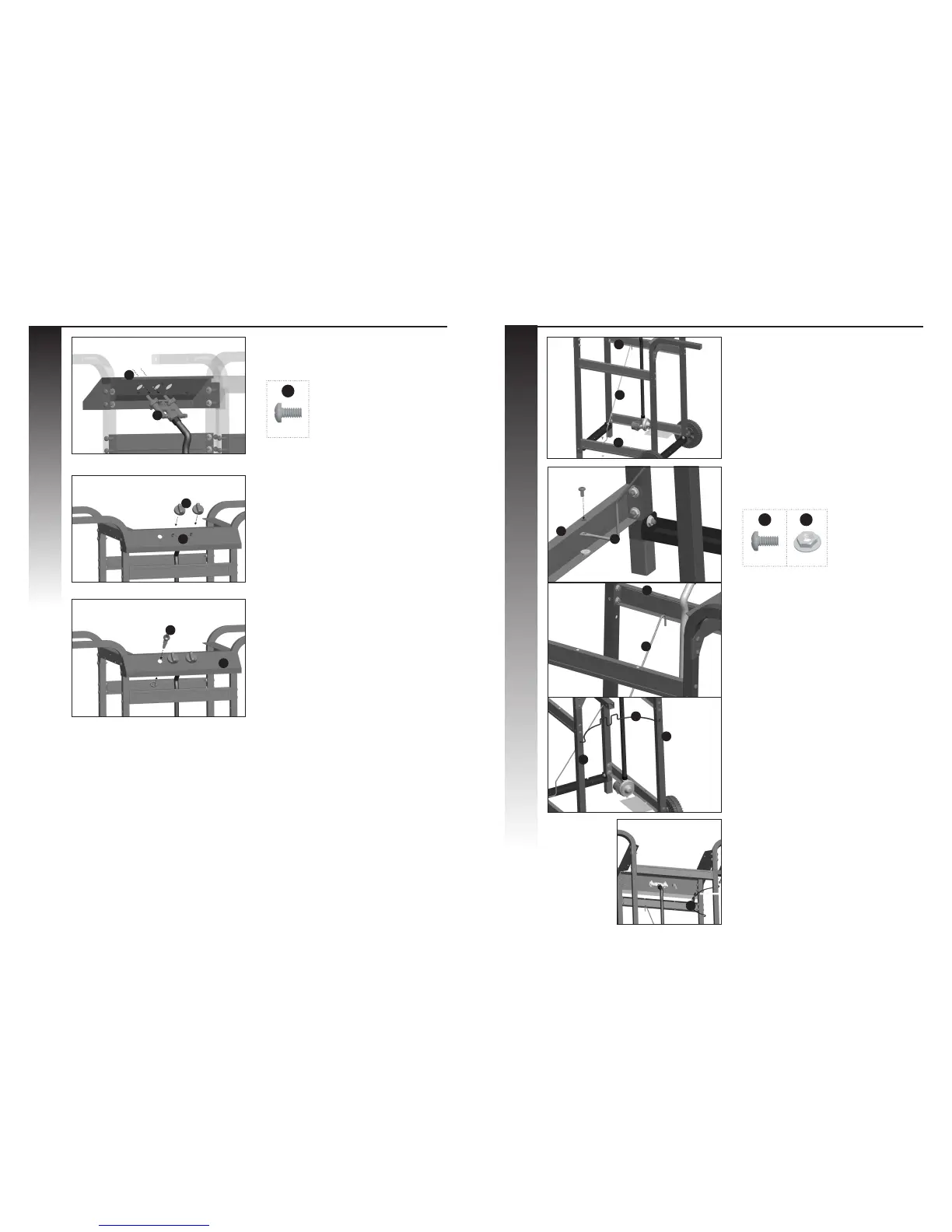
a. Position the valve assembly (CD) through the
back of the control panel (CA), and assemble.
b. Position the control knobs (CB) onto valve
stems (CD).
c. Assemble the igniter (CC) through the front of
the control panel (CA), as shown.
ASSEMBLY INSTRUCTIONS ASSEMBLY INSTRUCTIONS
5
a. Attach the tank exclusion (DG) to the upper
front support brace (DE) by hooking the end
of the tank exclusion into the hole provided,
on the inside of the cart.
b. Assemble the other end of the tank exclusion
(DG), to the lower back support brace (DE).
c. Attach the gas tank support (DF) to the left
cart legs (DA).
YOU WILL NEED:
6
X 2
VIEW FROM THE BACK OF THE CART ASSEMBLY
YOU WILL NEED:
6 7
X 1 X 1
CA
CD
CB
CC
DE
DE
DG
DE
DG
DE
DG
DF
DA
DA
DF
CD
CA