EasyManuals Logo

Master Forge RT2417S User Manual

Master Forge RT2417S
20 pages
To Next Page IconTo Next Page
To Previous Page IconTo Previous Page
Page #11 background imageLoading...
Page #11 background image
11
Lowes.com/masterforge
ASSEMBLY INSTRUCTIONS
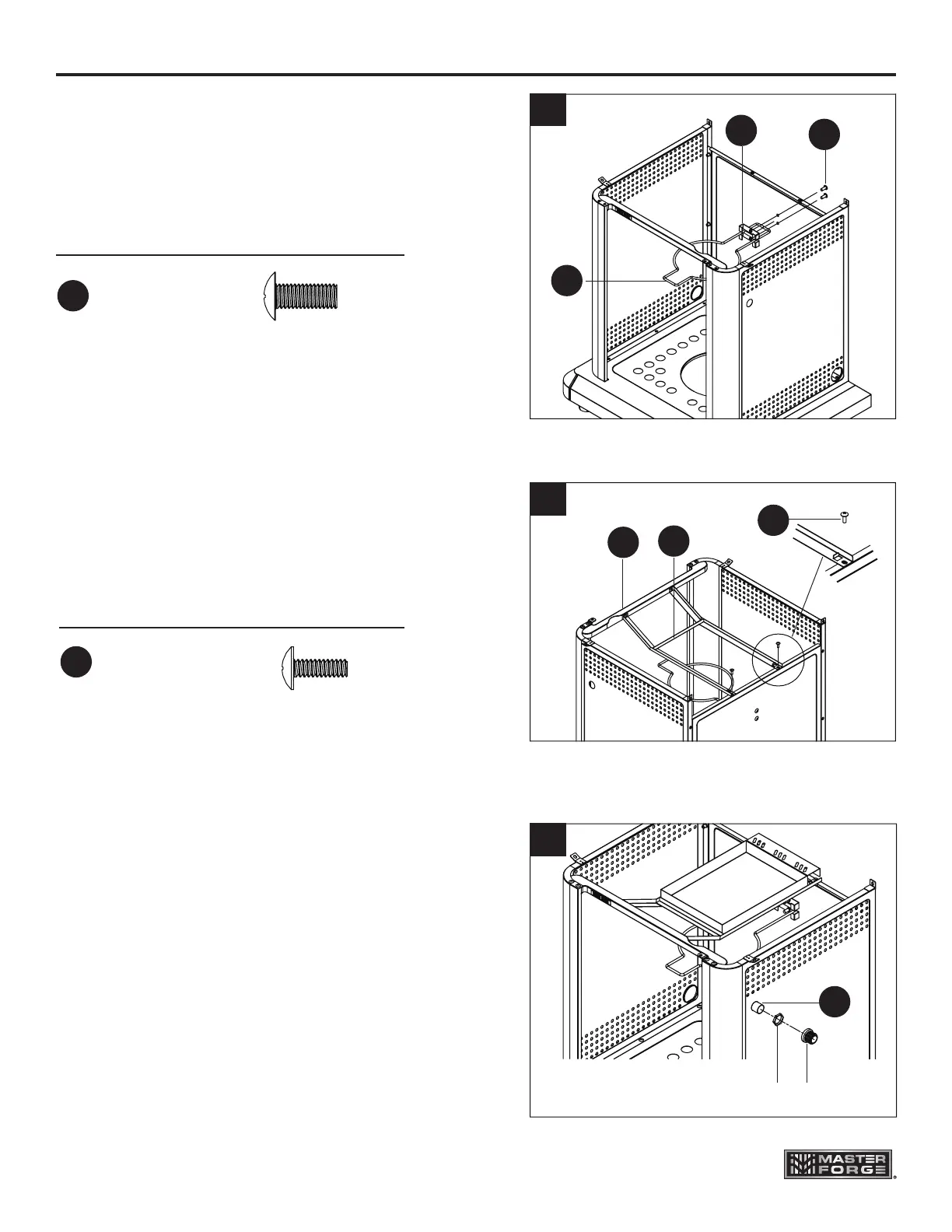
5. Slide the tank ring bracket (K) onto the end
of the safety tank ring (J) as shown. Attach
the tank ring bracket to the rear panel (L)
with 2 screws (BB) as shown.
6. Attach the drip tray support (I) to the front
beam (U) and rear panel (L) with 4 screws
(AA) as shown.
7. Remove the cap and the nut from the igniter
(M). Secure the igniter to the right panel (N)
with the nut. Then, reassemble the cap to
the igniter.
Hardware Used
AA
3/16-24 x 1/2 in.
Screw
x 4
Hardware Used
1/4 - 20x 5/8 in.
Screw
x 2
5
BB
BB
K
J
6
AA
U
I
7
Nut Cap
M

Other manuals for Master Forge RT2417S

Questions and Answers:

Question and Answer IconNeed help?

Do you have a question about the Master Forge RT2417S and is the answer not in the manual?

Master Forge RT2417S Specifications

General IconGeneral
BrandMaster Forge
ModelRT2417S
CategoryGrill
LanguageEnglish

Related product manuals