NOTE:
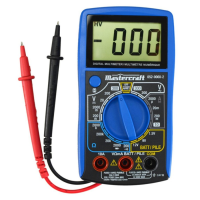
When the input is not connected, i.e. at open circuit, "1" will
be displayed as an overrange indication.
Before measuring in-circuit resistance, disconnect all power
to the circuit to be tested and discharge all capacitors
thoroughly.
2.
3.
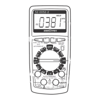
Continuity Test
Diode Test
Connect the black test lead to the "COM" terminal and the red
test lead to the "VΩmA" terminal.
Set the range switch to the position.
Connect the test leads across the circuit to be measured.
If the resistance is lower than about 30 Ω, the built-in buzzer
will sound.
Before test, disconnect all power to the circuit to be tested
and discharge all capacitors thoroughly.
Connect the black test lead to the "COM" terminal and the red
test lead to the "VΩmA" terminal (Note: The polarity of the red
test lead is positive "+").
Set the range switch to position.
1.
2.
3.
4.
1.
2.
model no. 052-0060-2 | contact us 1-800-689-9928
15
OPERATING INSTRUCTIONS