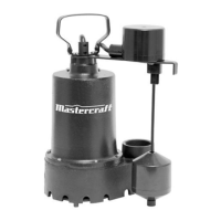
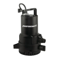
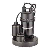
This document is an instruction manual for the Mastercraft Submersible SEWAGE PUMP, model no. 062-3429-6. It provides detailed information on the pump's specifications, safety guidelines, installation, operation, troubleshooting, and warranty.
Function Description
The Mastercraft Submersible SEWAGE PUMP is designed for transferring sewage water applications, i.e., transferring water with 2" (5 cm) suspended, stringy solids in it, and NOT to pump clear water from sump pits, hot water applications, water fountain/features applications, etc. It is a high-strength, corrosion-resistant pump suitable for long-time, heavy-duty, trouble-free service. The pump is not intended for use in swimming pools or in salt-water marine areas, nor is it designed as a "fountain" or "waterfall" pump. It should not be used in water containing fish, as it is an oil-filled motor pump. The pump features an automatic resetting thermal protector that automatically turns off the pump if it becomes too hot, preventing damage and voiding the warranty.
Important Technical Specifications
- Model Number: 062-3429-6
- Voltage: 115 V / 60 Hz
- Horsepower: 1/2 HP
- Amps: 9.5 A
- Max. Head: 27' (8.2 m)
- Max. Flow: 6000 U.S. GPH (22,713 L/h)
- Discharge Size: 2" (5.1 cm)
- Power Cord Length: 10' (3 m)
Performance Table:
| Head (m) |
5' (1.5 m) |
10' (3 m) |
15' (4.5 m) |
20' (6.1 m) |
Max. Head |
| GPH (L/h) |
6000 GPH (22,713 L/h) |
5000 GPH (18,927 L/h) |
4100 GPH (15,520 L/h) |
3300 GPH (12,492 L/h) |
27' (8.2 m) |
Usage Features
Installation:
The estimated assembly time for a new installation is 30 minutes (or longer if installing in a new sump pit). Materials required for assembly (not included) include thread-sealant tape, 2" (5 cm) check valve, 2" (5 cm) elbow, 2" (5 cm) union, 2" (5 cm) nipple pipe, and 2" (5 cm) gate valve. Tools required for assembly (not included) are a wrench and a cross-head screwdriver.
- Connecting a discharge pipe to the pump: Wrap the threads of the 2" (5 cm) discharge pipe (1) with thread-sealant tape. Attach the discharge pipe (1) to the discharge of the pump (2).
- Placing the pump in a basin: Place the pump on a hard surface inside a sewage basin.
- Connecting the check valve: Connect the discharge pipe (1) to the elbow (2), union (3), check valve (4), and gate valve (5).
Operation:
- Connecting power: Plug the pump power cord into the piggy-back switch plug outlet. Then, plug the switch plug into a 115 V GFCI power outlet. Allow the pump to operate through several on-off cycles.
- Operating the pump: When the float switch (1) moves up over the top of the pump, the pump begins to operate. When the water lowers to a certain level, the float switch (1) will turn the pump off.
Safety Precautions:
- Do not pump flammable or explosive liquids such as oil, gasoline, kerosene, ethanol, etc.
- Always disconnect the pump from its power source before installing, inspecting, maintaining, or repairing.
- Do not stand in water when the pump is connected.
- Do not touch the pump housing while it is operating, as the pump may be HOT and can cause serious skin burns.
- Do not disassemble the motor housing.
- The pump should be connected to a separate 15 A circuit breaker or 15 A fuse block.
- Periodically inspect the pump and system components to be sure the pump inlets are free of mud, sand, and debris.
- Wear safety glasses at all times when working with pumps.
- The unit is designed only for use on 115 V (single phase), 60 Hz, and is equipped with an approved 3-conductor cord and 3-prong grounded plug. DO NOT REMOVE THE GROUND PIN UNDER ANY CIRCUMSTANCES.
- Protect the electrical cord from sharp objects, hot surfaces, oil, and chemicals. Avoid kinking the cord. Do not use damaged or worn cords.
Maintenance Features
Troubleshooting:
The manual includes a comprehensive troubleshooting guide with common problems, possible causes, and corrective actions.
- Pump does not start or run:
- Possible Cause: Blown fuse, tripped breaker, plug disconnected, corroded plug, thermal overload, motor failed.
- Corrective Action: Replace fuse, reset breaker, secure plug, clean plug prongs, disconnect the pump from power for 30 minutes then reconnect, contact customer service for replacement.
- The pump runs but does not deliver water:
- Possible Cause: Check if the check valve is installed backwards, the impeller or volute openings are fully or partially clogged, the pump is air-locked, the inlet holes in the pump base are clogged, the vertical pumping distance is too high.
- Corrective Action: Arrow on check valve should point in direction of flow, remove and clean pump, start and stop several times by plugging and unplugging the cord, check for clogged vent hole in pump case or discharge pipe, remove and clean the opening, reduce distance or change discharge fittings.
- The pump runs and pumps out sump, but does not stop:
- Possible Cause: The float is stuck in the up position, the float switch is defective.
- Corrective Action: Replace the pump, reassemble the cover O-ring.
- The pump runs but only delivers a small amount of water:
- Possible Cause: The pump is air-locked, the vertical pumping distance is too high, inlet holes in the pump base are clogged, the impeller or volute openings are fully or partially clogged.
- Corrective Action: Start and stop several times by plugging in and unplugging the cord, check for a clogged vent hole in the pump case, reduce the distance or change the discharge fitting of the pump, remove the pump and clean the strainer and openings.
- The motor runs for a short time and then stops:
- Possible Cause: The inlet holes in the pump base are clogged, the pump impeller is partially clogged, the impeller or volute openings are fully or partially clogged.
- Corrective Action: Remove the pump and clean the openings, remove the pump and clean, remove the pump and clean. Also clean the strainer if one is installed.
Warranty:
This Mastercraft product carries a three (3) year LIMITED warranty against defects in workmanship and materials. This product is not guaranteed against wear or breakage due to misuse and/or abuse. The warranty is void if the pump is opened or repaired by the user, or if damage or personal injury occurs.
Key Parts Diagram:
The manual includes a diagram and parts list for easy identification of components:
- Head cover
- Piggy-back float switch
- Motor house
- Impeller
- Pump body