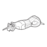
2. Match up key (2) on motor housing and slot (3) in
angle grinder attachment. There are also arrows on
the motor housing and angle grinder attachment
housing. Slide angle grinder attachment onto the
motor housing.
NOTE: While sliding angle grinder attachment onto
motor housing, rotate the angle grinder attachment
spindle (4) until flexible shaft adaptor engages into the
angle grinder attachment.
3. When flexible shaft adaptor is engaged into the angle
grinder attachment, slide angle grinder attachment
fully onto the motor housing as far as it will go.
4. Lock angle grinder attachment in place by pushing
quick-release lever until it snaps into place against the
angle grinder attachment housing.
5. Rotate angle grinder attachment guard (5) back
toward the motor so it will protect both your fingers
and the motor when grinding.
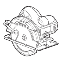
INSTALLING GRINDING DISC
1. Press angle grinder attachment locking button (1) and
rotate spindle nut (2) until the lock engages the shaft
(see Fig. 26).
2. Remove the spindle nut (if installed) by turning it
counter-clockwise with the collet wrench. Remove flat
washer (8).
3. Place the grinding disc (3) over the spindle (4).
NOTE: Loosen the slider screw (5) and adjust the
slider (6) if necessary to allow the grinding disc to fit
into the slot (7).
4. Re-install the flat washer and spindle nut on the
spindle and tighten in place.
NOTE: Do NOT over tighten the spindle nut. This may
cause the grinding disc to crack and shatter when the
angle grinder attachment is turned ON.
5. Re-tighten the slider screw so it holds the guide in the
correct position.
NOTE: Make sure the grinding disc does NOT touch
the guide when it turns.
INSTALLING GRINDING DISC – cont’d
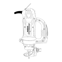
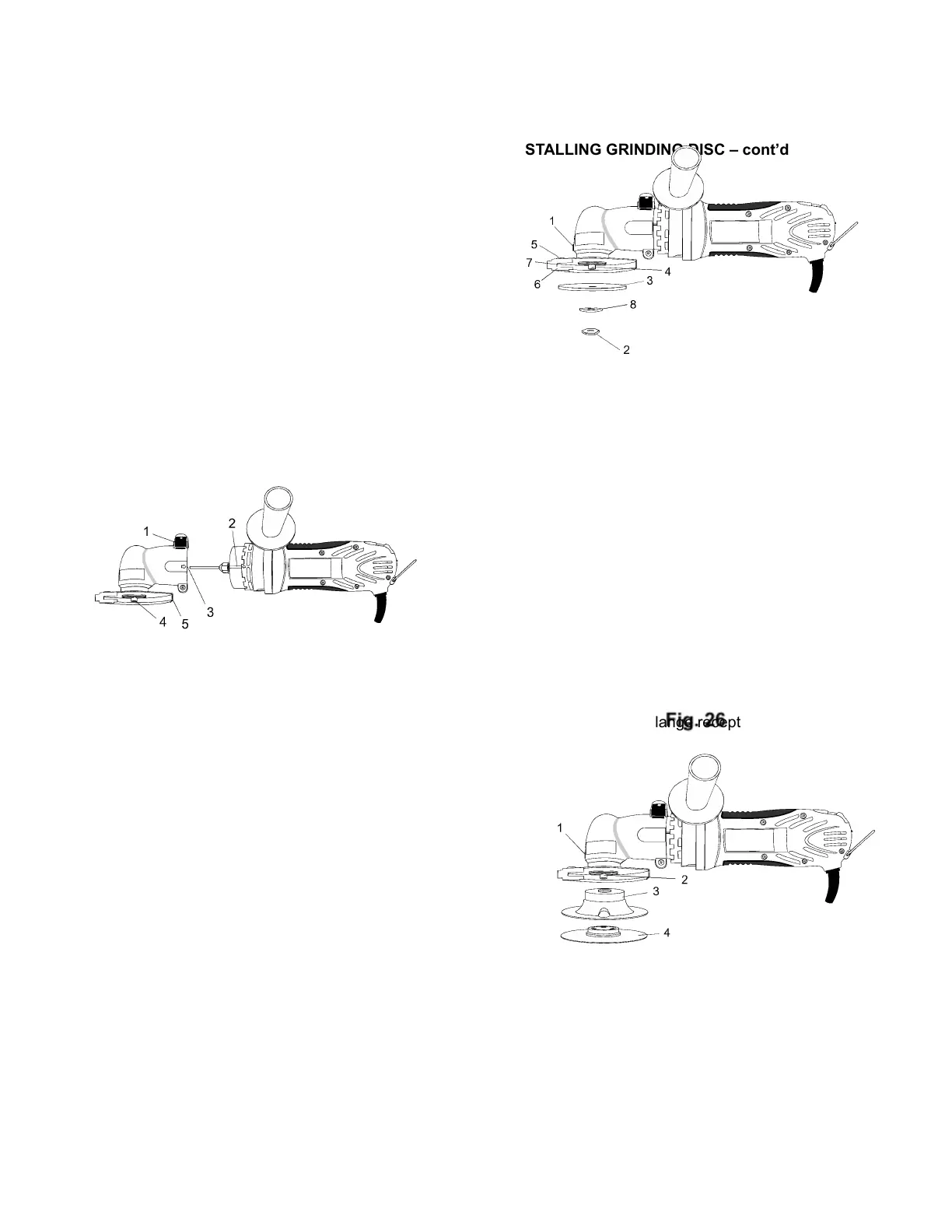
INSTALLING SANDING BACKING FLANGE & DISC
1. Press angle grinder attachment locking button (1) and
rotate spindle (2) until the lock engages the shaft (see
Fig. 27).
2. Remove the spindle nut (if installed) by turning it
counter-clockwise with the collet wrench. Remove flat
washer.
3. Install backing flange (3) onto spindle by turning it
clockwise.
NOTE: Only hand-tighten backing flange.
4. Place appropriate sanding disc (4) on the face of the
backing flange and lock into place by pressing the
centre into the backing flange and turning it clockwise.
NOTE: Make sure sanding disc hub securely locks
into the backing flange receptacle.