EasyManua.ls Logo

MasterCraft MIG 140

MasterCraft MIG 140
54 pages
To Next Page IconTo Next Page
To Previous Page IconTo Previous Page
Loading...
ASSEMBLY INSTRUCTIONS
27
MIG 140 INVERTER WELDER 058-9305-6
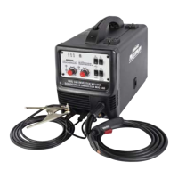
1. Place the shielding gas cylinder (1) (not
included) close to the welder
(fig P).
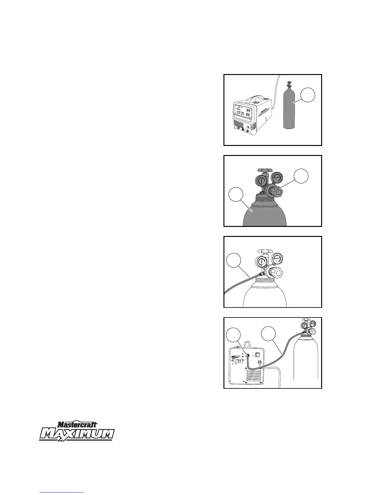
2. Attach the gas regulator (1) to the
shielding gas cylinder (2)
(fig Q)
.
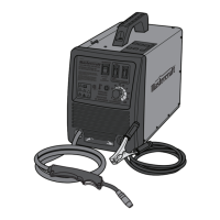
3. Connect one end of the gas hose (1) to
the regulator
(fig R)
.
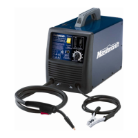
4. Attach the other end of the gas hose
(1) to the inert gas connection (2) on
the back panel of the welder
(fig S)
.
MC-589305-19
fig P
1
IGBT INVERTER WIRE FEED WELDER
SOUDEUSE DEVIDOIR INVERSEUR IGBT
4
5
6
7
8
9
10
V
V
POWE
R
ALI
M
E
NTA
TI
O
N
S
P
OOL
GUN
P
I
S
TO
L
E
T
À B
O
B
I
NE
MIG/
MIG
S
T
ICK
/B
AGUETTE
4
-STE
P
TEST GAS
058
-
9305
M
X
M
IG 140 INVERTER
W
I
RE
FIL
V
W
ORK
M
A
R
CH
E
ALARM
M
D
4
5
6
7
8
9
10
M
I
G/
M
I
G
2-
S
TEP
MC-589305-20
fig Q
250
300
350
400
0
10
50
100
150
200
20
30
40
50
1
2
MC-589305-21
fig R
250
300
350
400
0
10
50
100
150
200
20
30
40
50
1
MC-589305-22
fig S
250
300
350
400
0
10
50
100
150
200
20
30
40
50
GAS INPUT
ENTRÊE DE GAZ
110V - 120V
1PH
OFF
ON
MARCHE
ARRÊT
POWER
PUISSANCE
2
1

Table of Contents

Related product manuals