ASSEMBLY INSTRUCTIONS
22
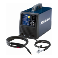
MIG 180 INVERTER WELDER 058-9306-4
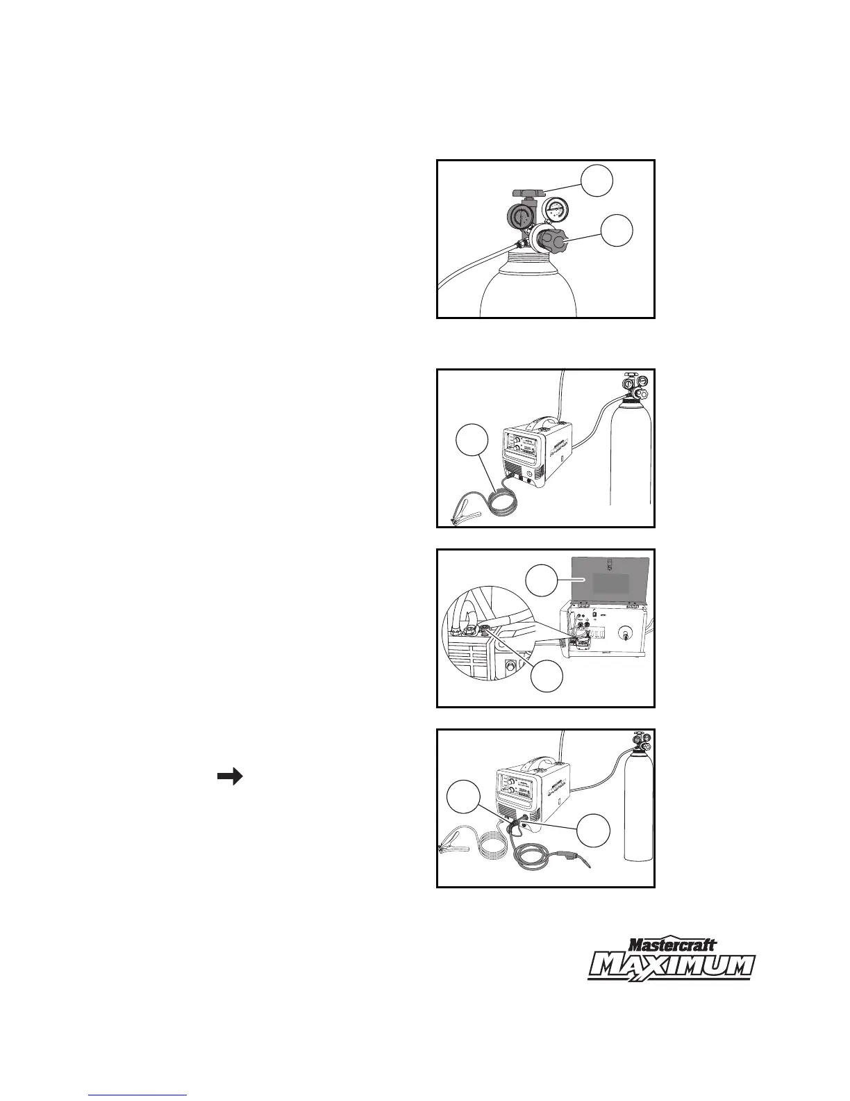
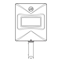
5. Open the valve (1) of the shielding gas
cylinder and adjust the flow rate using the
regulator (2) to 20 cubic feet/hour
(fig 1L)
.
Note: The red scale of the regulator denotes the
flow rate.
Note: Gas flow can be heard at the end of the gun
when the trigger is activated.
Note: If there is no gas flow, harsh arc with
excessive spatter will occur and a smooth weld
bead will not be obtained.
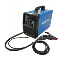
6. Plug the ground cable (1) into the
ground cable connection of the welding
unit
(fig 1M)
.
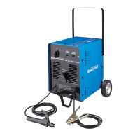
7. Open the wire drive compartment door (1)
and loosen the gun securement screw
(2)
(fig 1N)
.
8. Attach the MIG gun (1) and MIG gun
trigger cable (2) to their designated
connections
(fig 1O)
. Refer to Important
information page 13.
MC-589306-21
fig 1L
1
2
MC-589306-22
250
300
350
400
0
10
50
100
150
200
20
30
40
50
9
9
3
4
5
6
7
8
WI
RE
STI
C
K
A
10
3
4
5
6
7
8
10
POW
ER
WA
RNI
NG
W
O
RK
V
A
S
TIC
K
MIG
GAS INERTE
MIG
V
GA
S
INERT
E
ARC
A
RC
FI
L
MAR
C
HE
058
-930
6
-4
AV
ERTISS
E
M
EN
T
IN
T
ENSITÉ
MIG 180 INVERTER WELDER
SOUDEUSE À ONDULEUR MIG 180
fig 1M
1
WAR
N
I
NG /
A
VE
RT
I
SSEMEN
T
E
LECTRIC SH
OC
K
can kill
UN CHOC ÉLECTRI
QU
E
peut tuer.
MOUING PA
R
TS ca
n
c
a
use
in
jur
y
.
LES PI
ÉCES MOBILES
peuvent cau
ser
des blessures.
• Weld
ing wire an
d
d
r
iv
e
parts may
be
at
w
eldin
g
vol
t
age
.
•
Keep
away
fr
o
m m
o
v
i
n
g
parts
.
•
N
e v
o
u
s approchez p
a
s des
pièces mobi
les
.
• Maint
e
n
ez tous les couv
e
r
cles,
pan
n
eau
s
et
po
r
t
es
fermés
et
s
olid
e
m
ent e
n
p
l
a
ce
.
•
Kee
p
a
ll
do
o
rs,
cove
rs and panels
clos
ed an
d securely
in p
lace
.
•
Le fil de s
o
u
dure et les
pièces m
o
trices
s
o
n
t
peu
t
-ê
t
re
a la
tension de s
oudage.
•
N
e
t
ouch
e
z
pas
l
e fil oules
p
ar
ties
motrices à main
s
n
ues
ou
a
ve
c
des
o
u
tils l
o
rsque
la deten
te
e
st sou
s
, pr
e
ssion.
•
D
o
n
o
t
t
o
u
ch
wire
o
r drive
par
ts with bare h
a
n
ds
o
r tools
w
h
e
n
trig
ger is
depr
e
s
s
e
d
.
MIG
SPOOL GUN/PISTOLET À BOBINE
Whe
n normal MIG welding,
this switch should be turned in “MIG” position.
when using spool gun.
this switch should be in “Spool gun”
position.
Ce commutate
ur doit être placé à la position « MIG »
si vous effectuez du soudage MIG n
o
rmal
et à la position « SPOOL GUN »
si vou
s
utilisez un pistolet à bobine.
D
C
EN
DC
E
N
F
L
UX
C
O
RE
WIRE
FIL AVEC ÂME
E
N
F
LU
X
C
o
u
r
an
t
cont
i
nu
p
ol
ar
i
t
é
n
or
m
a
l
e
Pol
ar
i
t
y
swi
t
ch
s
e
tt
i
n
g:
Régl
a
ge
d
u
commu
tate
u
r
d
e
pola
r
i
té:
Di
r
e
ct
c
ur
re
nt,
e
lectrod
e
n
agat
i
v
e
DCE
P
DC
EP
MIG
MIG
Direct
current,
ele
ctrode
positive
C
o
urant
con
tinu,
elec
trode
posit
iv
e
Pola
r
i
t
y
s
w
itch
s
et
ting:
R
églag
e du commuta
teu
r
de pol
arité:
ST
IC
K
BAGUETTE
Po
larity
switch setti
ng
:
R
é
glage
d
u
c
o
mm
ut
a
t
e
ur d
e
po
larité
:
+
+
+
-
-
-
NO GAS/PAS DE GAZ
GAS/GAZ
UN CHOC ÉL
MOUING PARTS can caus
LES PIÉCES MOBILES peuve
• Keep away from moving parts.
• Ne vous approchez pas des pièces mobiles.
• Maintenez tous les couvercles, panneaus et po
solidement en place.
• Keep all doors, covers and panels closed
• Le fil de soudure et les piè
tension de soudage.
• Ne touchez pas le fil oules parties
avec des outils lorsque la detente e
trigger is .
1
2
MC-589306-23
fig 1N
MC-589306-24
250
300
350
400
0
10
50
100
150
200
20
30
40
50
9
9
3
4
5
6
7
8
WIRE
MIG
V
STICK
A
10
3
4
5
6
7
8
10
POW
E
R
W
A
RNING
WORK
V
A
ST
I
CK
F
IL
GAS INE
R
TE
M
IG
GA
S
INE
ARC
AR
C
fig 1O
1
2
AVERTISSEMENT
MARC
H
E
INTENSITÉ
058-9306-4
MIG 180 INVERTER WELDER
SOUDEUSE À ONDULEUR MIG 180