ASSEMBLY INSTRUCTIONS
21
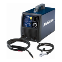
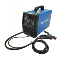
MIG 180 INVERTER WELDER 058-9306-4
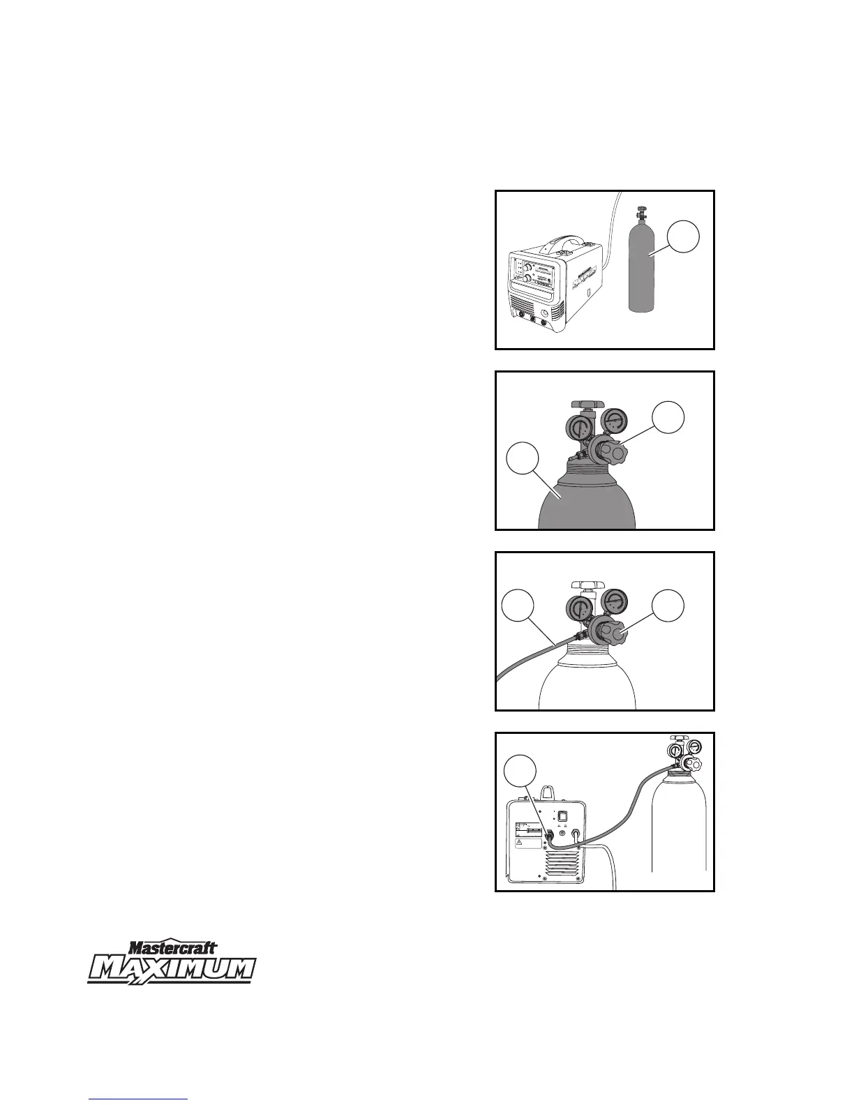
Installation for MIG welding
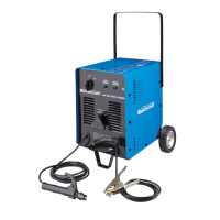
1. Place the shielding gas cylinder (1) (not
included) close to the welding unit
(fig 1H).
2. Attach the regulator (1) to the shielding
gas cylinder (2)
(fig 1I)
.
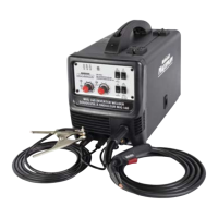
3. Connect one end of the gas hose (1) to
the regulator (2)
(fig 1J)
.
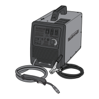
4. Attach the other end of the gas hose (1)
to the inert gas connection on the back
panel of the welding unit
(fig 1K)
.
MC-589306-17
fig 1H
1
9
9
3
4
5
6
7
8
WIRE
S
TICK
A
10
3
4
5
6
7
8
10
POWER
W
A
RNING
W
O
RK
V
A
STIC
K
MIG
G
A
S I
NE
R
TE
M
IG
V
G
A
S INER
T
E
A
RC
A
RC
F
IL
MA
RC
HE
058-9306-4
A
V
ERT
I
SSE
M
ENT
INTENSITÉ
MIG 180 INVERTER WELDER
SOUDEUSE À ONDULEUR MIG 180
MC-589306-18
fig 1I
250
300
350
400
0
10
50
100
150
200
20
30
40
50
1
2
MC-589306-19
fig 1J
250
300
350
400
0
10
50
100
150
200
20
30
40
50
1
2
MC-589306-20
fig 1K
250
300
350
400
0
10
50
100
150
200
20
30
40
50
GAS INPUT
ENTRÊE DE GAZ
NORMAL
NORMAL
OFF
ON
MARCHE
ARRÊT
POWER
PUISSANCE
OVER CURRENT
SURINTENSITEE
ELECTRICAL WARNING
AVERTISSEMENT RELATIE À L’ÉLECTRICITÉ
• Disconnect from power supply before servicing.
• Do not operate with any panels or covers removed.
• Débranchez le cordon de la source d’alimentation avant l’entretien.
• Ne faites pas fonctionner cet appareil avec les panneaux ou les couvercles retirés.
• L’entretien de cet appareil doit toujours être effectué par un technicien Qualifie.
• Service on this machine should only be performed by
a Qualified technician.
MIG
GAZ INERTE
STICK
ARC