ASSEMBLY INSTRUCTIONS
24
MIG 180 INVERTER WELDER 058-9306-4
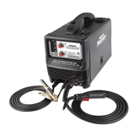
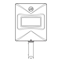
16. Turn ON the primary power switch (1) on
the back panel of the welding unit
(fig 1T)
. Refer to MIG welding operation
page 30.
Installing the wire roller
1. Open the wire drive compartment.
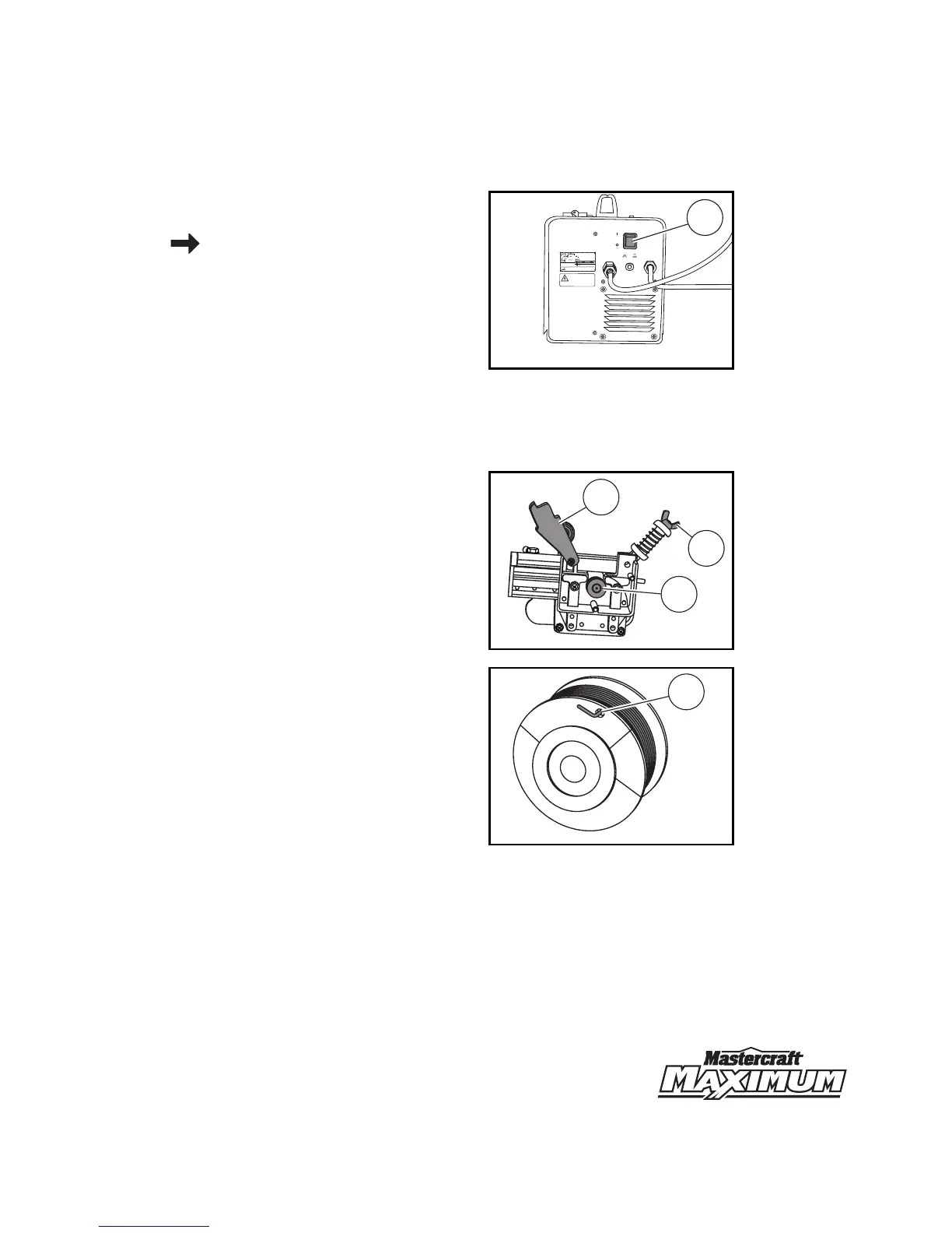
2. Remove the drive tension by loosening
the drive tension adjusting knob (1) and
lifting the drive tension adjustor and
drive tension arm (2) away from the
drive roll (3)
(fig 1U)
.
Note: Proper sized drive roll must be used
before installing the wire.
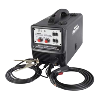
3. Insert the end of the wire (1) into the hole
on outside edge of the wire spool and
bend the wire to hold the wire in place.
Remove the wire spool from the wire
drive compartment
(fig 1V).
Note: If the wire is already installed in the
welder, roll the wire back onto the wire spool
by manually rotating the wire spool clockwise.
Do not allow the wire to come out of rear end
of the inlet guide tube.
MC-589306-29
fig 1T
GAS INPUT
ENTRÊE DE GAZ
NORMAL
NORMAL
OFF
ON
MARCHE
ARRÊT
POWER
PUISSANCE
OVER CURRENT
SURINTENSITEE
1
ELECTRICAL WARNING
AVERTISSEMENT R
E
LATIE À L’ÉLECTRICITÉ
• Disconnect fr
o
m p
o
we
r
supply b
ef
or
e s
erv
i
cing.
• Do not operate w
ith
any
panels or co
v
ers
r
emo
v
ed.
• Dé
b
ra
n
chez
l
e c
o
rd
on de la
s
ou
r
ce
d
’
a
limen
t
at
io
n avant l
’en
t
ret
i
en.
•
Ne fait
es
pas fonctionner ce
t
app
a
reil avec les panneaux ou le
s
co
u
vercl
e
s
r
etirés.
•
L’entretien
d
e cet appareil doit
to
ujo
ur
s ê
tr
e effect
ué
par
un t
echnic
i
en
Q
ua
l
ifie.
• Servic
e
on th
i
s machine sho
u
ld onl
y
b
e
perf
o
rm
ed by
a Q
u
alified
t
ec
h
nician.
MIG
GAZ INERTE
STICK
ARC