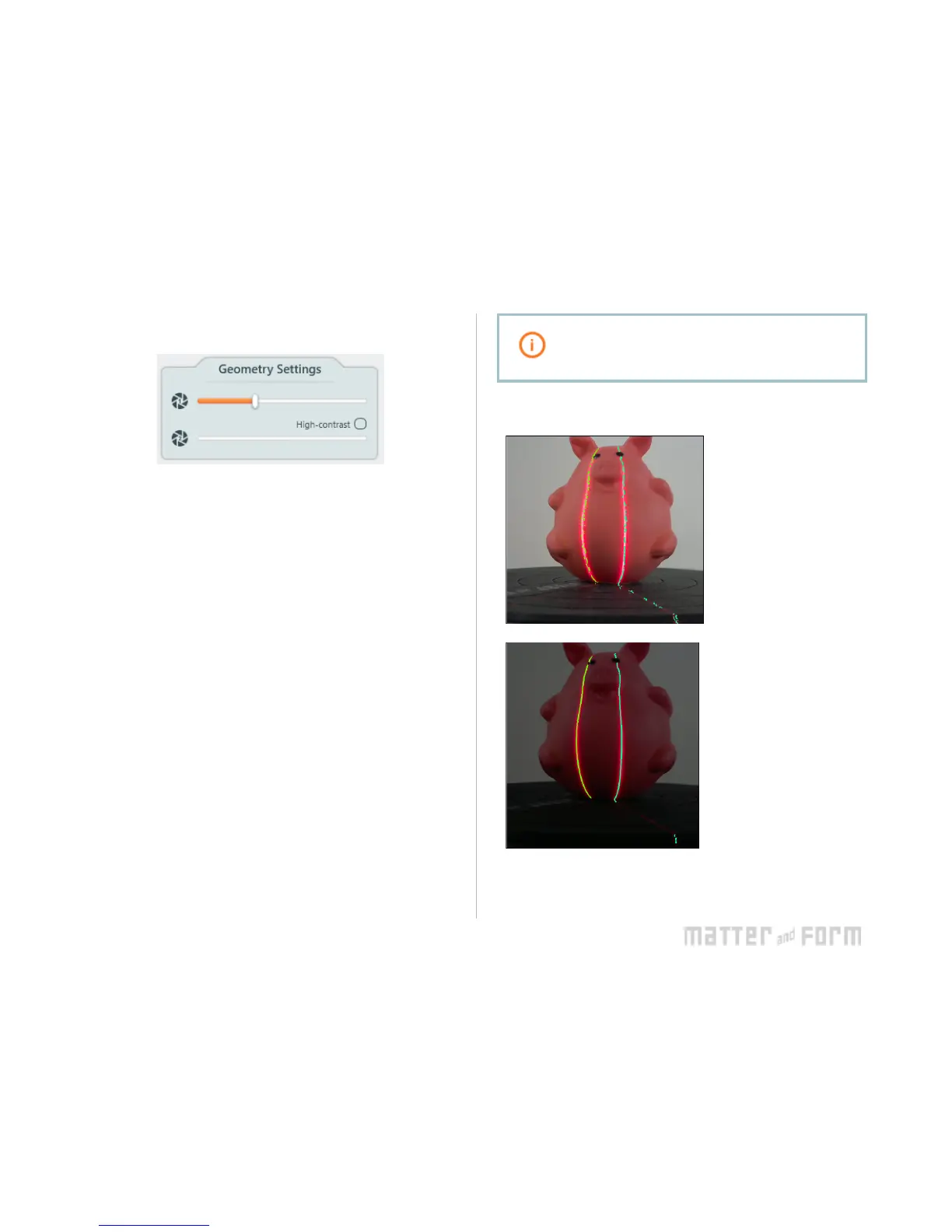
Geometry Settings
The Geometry Settings can be found at the top of the Scan
Setup sidebar. The slider controls the camera’s exposure,
making the laser lines visible for capturing an object. Laser
lines will bounce off different colours and object materials
differently, influencing how well it will capture information.
Changing the camera’s exposure can make the lasers more or
less visible.
One or two red lasers will be visible in the camera view. The
additional green overlay represents how the scanner sees the
lasers, ie. where your object is being detected. Adjusting the
Geometry Settings slider will change how easy it is for the
scanner to see the lasers.
To find the best exposure for your object, choose an
exposure where the green overlay is a sharp line, meaning
that it doesn’t have a lot of noise. Noise appears as fuzzy
static rather than a straight solid or nearly solid line. The
more defined and filled in the laser line the better the results.
If your laser line detection is poor at every exposure, adjust
your lighting environment.
Dark-colored areas need a bright camera exposure
and light-colored areas need a darker camera
exposure for the best laser line detection.


 To Next Page