H-Series User Manual Rev2021A 3
Installation - Mechanical
ANSI Flanges: Using H-Series meters at pressures greater than 500 psi (35 bar) requires anges. See the specications
and bolt torque table below. Max bolt kits are available for ange installations. Always use process uid compatible
lubricant on the o-ring to attach the tting to the meter.
Customer supplied angesMax Flange Bolt and Stud Kit
Max H-Series Meter
Meter
(Flange size)
Studs Torque For Line Pressure ft-lb (N-m)
See notes below
Qty Size 500 psi (35 bar) 3500 psi (245 bar)
H241LS (Class 600 Flange) 4 3/4”-10 24 (33)
H241MS* (Class 2500 Flange) 4 1-1/8”-7 256 (247)
H242LS (Class 900 Flange) 8 3/4”-10 24 (33)
H242MS* (Class 1500 Flange) 8 1”-8 219 (297)
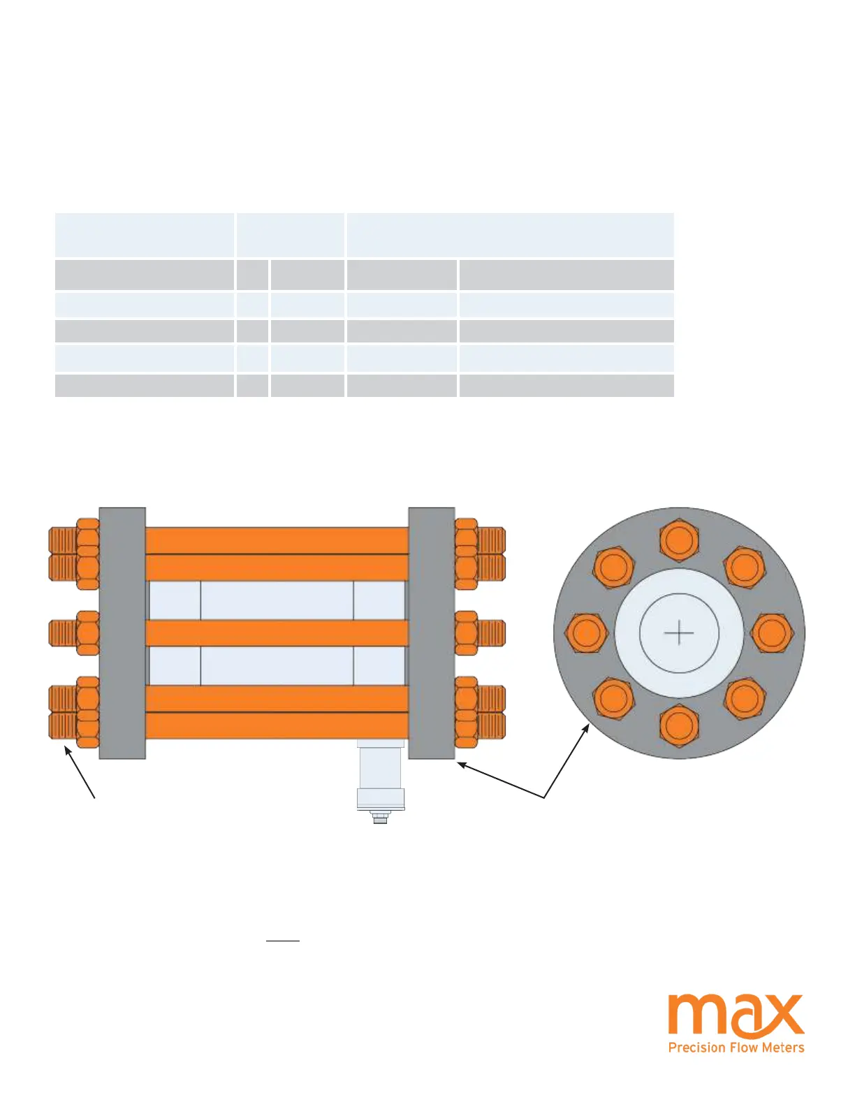
ANSI Flange Stud Torque Requirements: This table shows the minimum torque required for a 2:1 tightening factor at
the indicated pressures using zinc plated studs and nuts.
Notes:
H-Series meters that are designated as “LS” may be mounted using their NPT treads.
For convenience, wafer style mounting can be made using the ange size and bolt specications listed above.
* Meters that are marked as “MS” must be mounted between anges. The studs and nuts listed in the table are provided
for use with the customer supplied anges.
ANSI Flange Diagram