H-Series User Manual Rev2021A 4
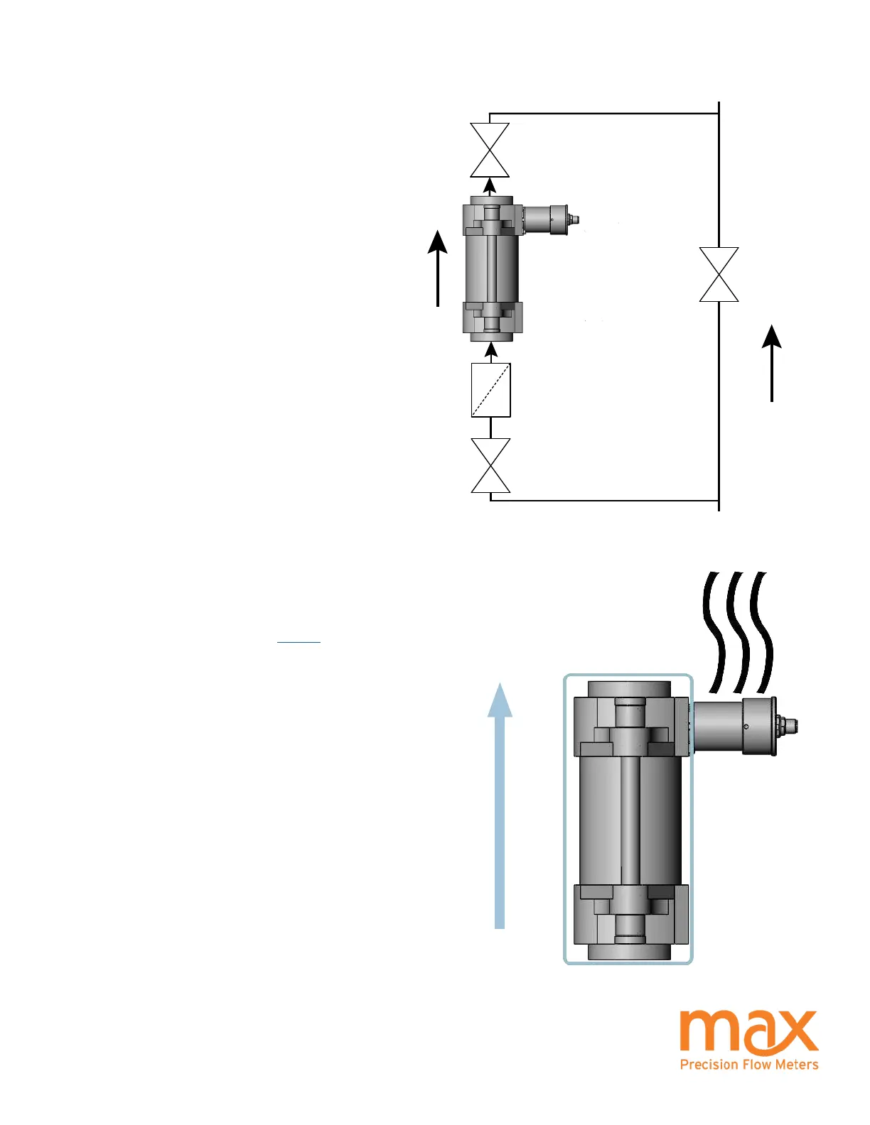
Bypass Valves: Install valves to allow system start-
up, lter replacement, or ow meter removal without
completely shutting the system down and draining the
lines. See diagram.
Failure to use a bypass at start up may lead to ow meter
damage due to debris, overspeeding the meter with air in
the lines, and pressure shock due to initial line surges.
Filtration: A 150 micron lter is recommended on the
inlet for all H-Series ow meters. If measuring bi-
directional ow, a lter should be installed on both sides
of the ow meter. Materials with high viscosity or brous
or non-abrasive particulate matter may need to be run
without lters.
Clean Plumbing: Before installing the ow meter, the
system lines shall be cleaned and free of all debris
or manufacturing particulates. Purging lines with
compressed air or steam are typical cleaning methods.
Do not use compressed air or steam on the Max ow
meter, damage will occur.
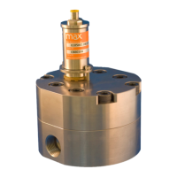
High Temperatures: Orient your meter so the transmitter is to the side
or below to minimize heat transfer by convection from the ow meter
to the transmitter. The transmitter is the most heat sensitive element
in the system. Consult the chart on page 9 for specic limits on uid
and ambient maximum temperatures. When operating in the upper
temperature ranges, always insulate the meter but leave the transmitter
housing exposed so it radiates heat. Optional heat tracing can be
used on the ow meter to keep it at the uid operating temperature.
For substances solid at room temperature, heat tracing may be
required to keep material molten to ow through the meter.
Installation - Mechanical
Valve #2
Valve #1
Valve #3
Bypass
Filter
Flow
Flow
FLOW
INSULATION HERE
RADIATE HEAT HERE