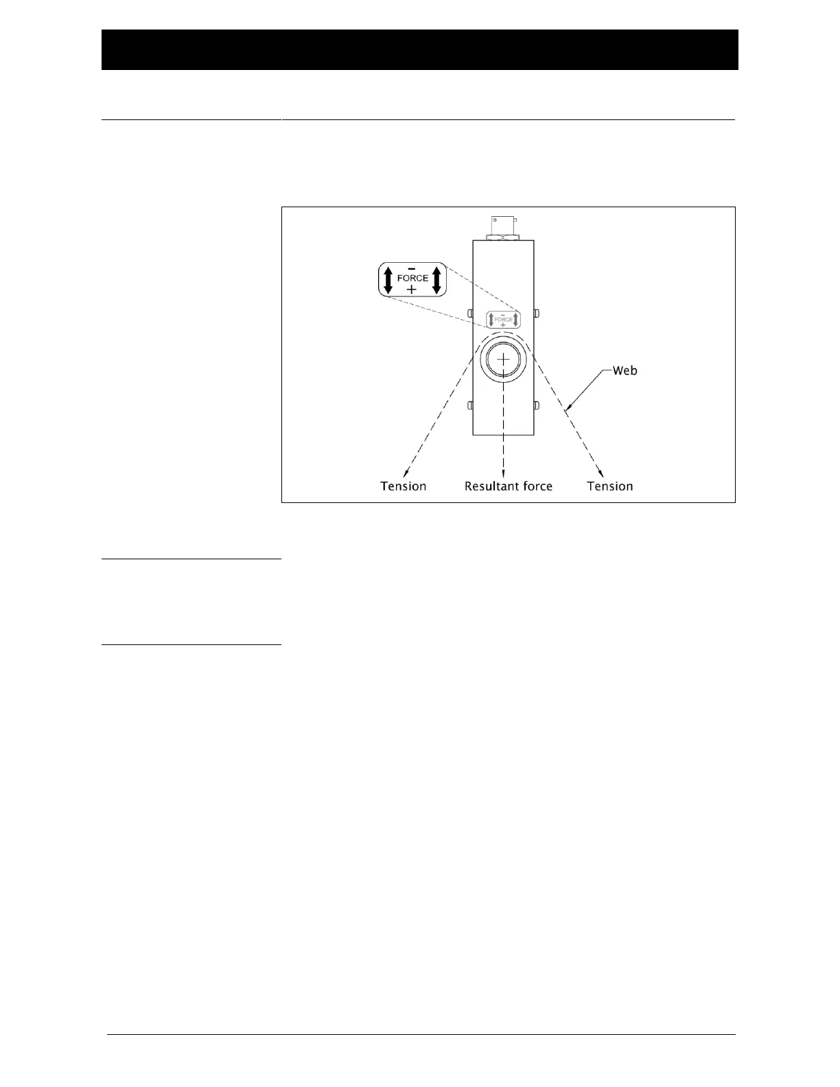
The force direction arrow should also bisect the wrap angle of the
web, and point in the same direction as the resultant tension
force as shown in
Figure 2.
1. Insert the customer’s shaft and roll assembly into the CL
Load Cell as shown in
Figure 1; page 5-1
.
2. Make sure that neither the shaft nor the roll will interfere
with the CL load cell housing or the machine side frame.
For outside frame mount, the minimum clearance hole
diameter in the machine side frame is:
CL1 models 17.5 mm [0.69 inch]
CL 2 models 26.9 mm [1.06 inch]
3. Tighten all four set screws securely against the shaft.
4. Connect the CL load cell to the control with shielded cable.