The Fife-200 Web Guiding System is a small web guide and controller designed for continuous use, capable of controlling four guides and sensors, and an operator interface. It is suitable for installation as Partly Completed Machinery into a machine or partly completed machine, and complies with the 2006/42/EC Machinery directive and the 2004/108/EC Electromagnetic Compatibility directive. The system is designed for professional installation, operation, and maintenance by qualified personnel.
Function Description:
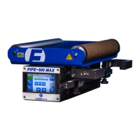
The Fife-200 Web Guiding System consists of three main parts: an offset pivot guide, a sensor, and a controller. The controller is capable of managing four guides and sensors and an operator interface. It has one sensor input per guide, three parallel inputs per guide, and one parallel output per guide. The controller manages all guides through a color touch-screen operator interface. The controller parallel inputs and outputs are used for remote control and alarms. The system monitors the web position with a sensor mounted in the web path and drives an actuator connected to the guide assembly to steer the web to the desired position. The Fife-200 Battery Guiding System can operate in Servo-Center mode without a Servo-Center sensor for centering the guide while threading the web. When entering Servo-Center mode, the guide will jog between mechanical stops and center at the midpoint of the stops. The Fife-200 Web Guiding System is compatible with most Fife sensors.
Important Technical Specifications:
- Operating Temperature: 0° to 50° C [32° to 122° F]
- Ingress Protection Class: IP40
- RoHS: Compliant
- Power Cable Length: 5 m [16.4 ft]
- Motor Cable Length: 5 m [16.4 ft]
- Sensors Cable Length: 5 m [16.4 ft]
- Digital Input/Output Port Cable Length: 10 m [32.8 ft]
- Operator Interface Cable Length: 20 m [65.6 ft]
- Maximum Web Tension: 49 N [11 lbs]
- Correction Speed:
- 60 x 60: 61 mm/s [2.4 in/s]
- 110 x 110: 67 mm/s [2.6 in/s]
- 140 x 140: 76 mm/s [3.0 in/s]
- 200 x 200: 81 mm/s [3.2 in/s]
- Correction Range: +/- 12 mm [0.47 in] for 60x60 guide, +/- 10 mm [0.39 in] for 60x60 guide (this appears to be a typo in the manual, likely referring to different guide sizes for the second value)
- Weight:
- 60 x 60: 2.5 kg [5.5 lb]
- 110 x 110: 3.6 kg [8.0 lb]
- 140 x 140: 4.4 kg [9.8 lb]
- 200 x 200: 5.7 kg [12.65 lb]
- Motor: 24 VDC brushless
- Controller Input Voltage Range: 22.5 to 26.4 VDC
- Supply Current: 5 A maximum
- Internal Fuse: 10 A, slow-blow
- Controller Dimensions:
- Height: 62 mm [2.44 in]
- Width: 147 mm [5.79 in]
- Length: 260 mm [10.24 in]
- Product Certifications: CE, TUV Rheinland of North America to UL61010-1 and CAN/CSA-C22.2 No. 61010-1 and CB Certificate to IEC61010-1
- Inputs and Outputs:
- Number of guides controlled: Four (two when using SE-26A)
- Sensor Input (four): One per guide, Max input +/-20 mA, individually programmable, 0 to 10 mA (preferred)
- Digital Port: 12 digital inputs, three per guide, Active high, Low level: 0 to 0.9 V, High level: 3.5 to 24 V
- Digital Outputs: Four outputs, one per guide, Open collector, 55 mA at 1.6V saturation, Maximum +30 VDC applied to output, +12 V available to port for input reference
- Supply to accessories: +12 V +/-5%, 600 mA maximum; -12 V +/-5%, 80 mA maximum
Usage Features:
- Installation: The web guide is mounted on a rigid support frame using four M8 bolts through 9 mm [0.35 in] diameter holes. Various mounting dimensions are provided for different roll face and guide span combinations.
- Wrap Styles: The manual illustrates several allowed wrap styles for threading the web through the guide.
- Sensor Installation (SE-47): The SE-47 amplifier is mounted on a 35 mm DIN rail. Fiber optic cables are trimmed to length using a supplied cutting tool and then installed into the amplifier. Sensor head position is adjusted by loosening a set screw and turning an adjustment knob.
- Other Fife Sensor Installation: Other standard Fife sensors (SE-11, SE-22, SE-44R, SE-31, SE-26A) are mounted in the web path on a customer-supplied support frame.
- Operator Interface Installation: The operator interface can be panel-mounted or wall-mounted. Installation kits are available for both configurations.
- Electrical Installation: Cables are installed into the controller housing by removing hole plugs from the end plates. The protective earth connection (PE) uses a green wire terminal from the power cable, connected to the inside of the power entry end plate.
- Controller Connection Diagrams: Detailed diagrams are provided for connecting sensors, motors, and I/O cables for different sensor types (SE-47, SE-11, SE-22, SE-44R, SE-31, and SE-26A).
- Digital Inputs/Outputs: Three digital inputs and one output are available per guide for remote control and signaling functions. Inputs can be configured for External Lock, Automatic, and Manual modes. The digital output is initially configured for an alarm for Loss of Null for each guide.
- Safety: The manual emphasizes proper transportation, storage, installation, operation, and maintenance. It includes warnings about general hazards, crushing, cutting, electric shock, hot surfaces, unexpected movement, and the importance of providing mechanical support for electrical cables to prevent strain.
Maintenance Features:
- Maintenance Schedules: Recommended intervals are provided, with adjustments based on ambient conditions.
- General Maintenance: The motor of the Fife-200 guide requires no maintenance.
- Sensor Cleaning: Sensors should be cleaned as necessary to ensure clear visibility of the menus. This involves wiping down components with a clean and dry cloth.
- Operator Interface Cleaning: The touchscreen should be cleaned as necessary to ensure clear visibility of the menus. Cleaning involves wiping down components with a clean and dry cloth. Commercial liquid cleaner may be used if necessary, ensuring a small amount is placed on the cloth before wiping. Do not directly spray the screen. Compressed air or a shop vacuum may also be used.
- Replacement Parts: Information on how to request service or replacement parts is provided, including contact details for Maxcess International offices in Oklahoma (USA), Europe (Germany), and Zhuhai (China). When ordering replacement parts, the possible part number, drawing number, and model description should be provided.
- Shipping for Service: If the system needs to be returned for service, care must be taken to properly package the unit to prevent damage during shipment. Original shipping containers should be used if possible.