Reassemble the controller enclosure
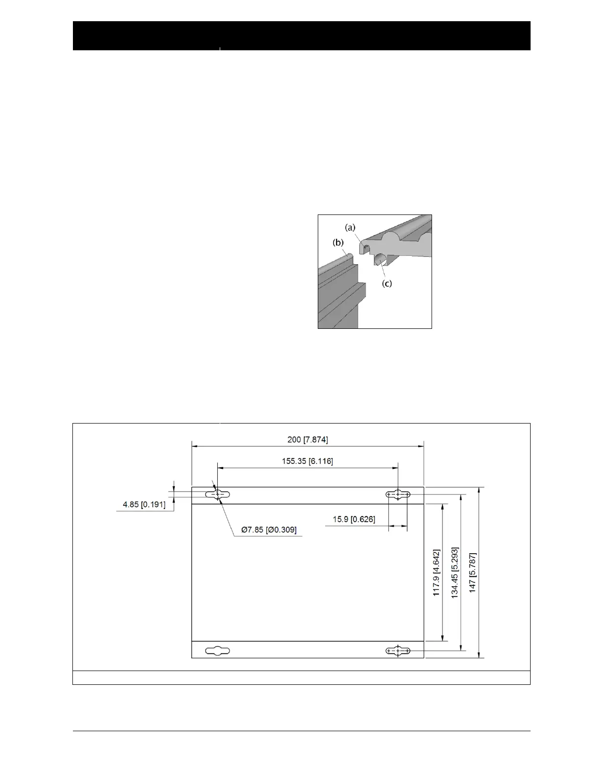
1. Re-install the controller housing cover by sliding it onto
the controller housing base. Make sure that the outside
groove (a) on the housing cover aligns with the top edge
of the base (b). The threaded opening (c) is for the screws
that secure the end plates to the assembly.
2. Attach the end plates to the controller housing base and
secure with the eight M3 flat head screws.
3. Mount the assembled controller to a rigid frame with four
M6 bolts in the controller mounting holes shown in
Figure 16.