16
6.4 CONTROLS DESCRIPTION
This crane is fitted with a standard cable remote control.
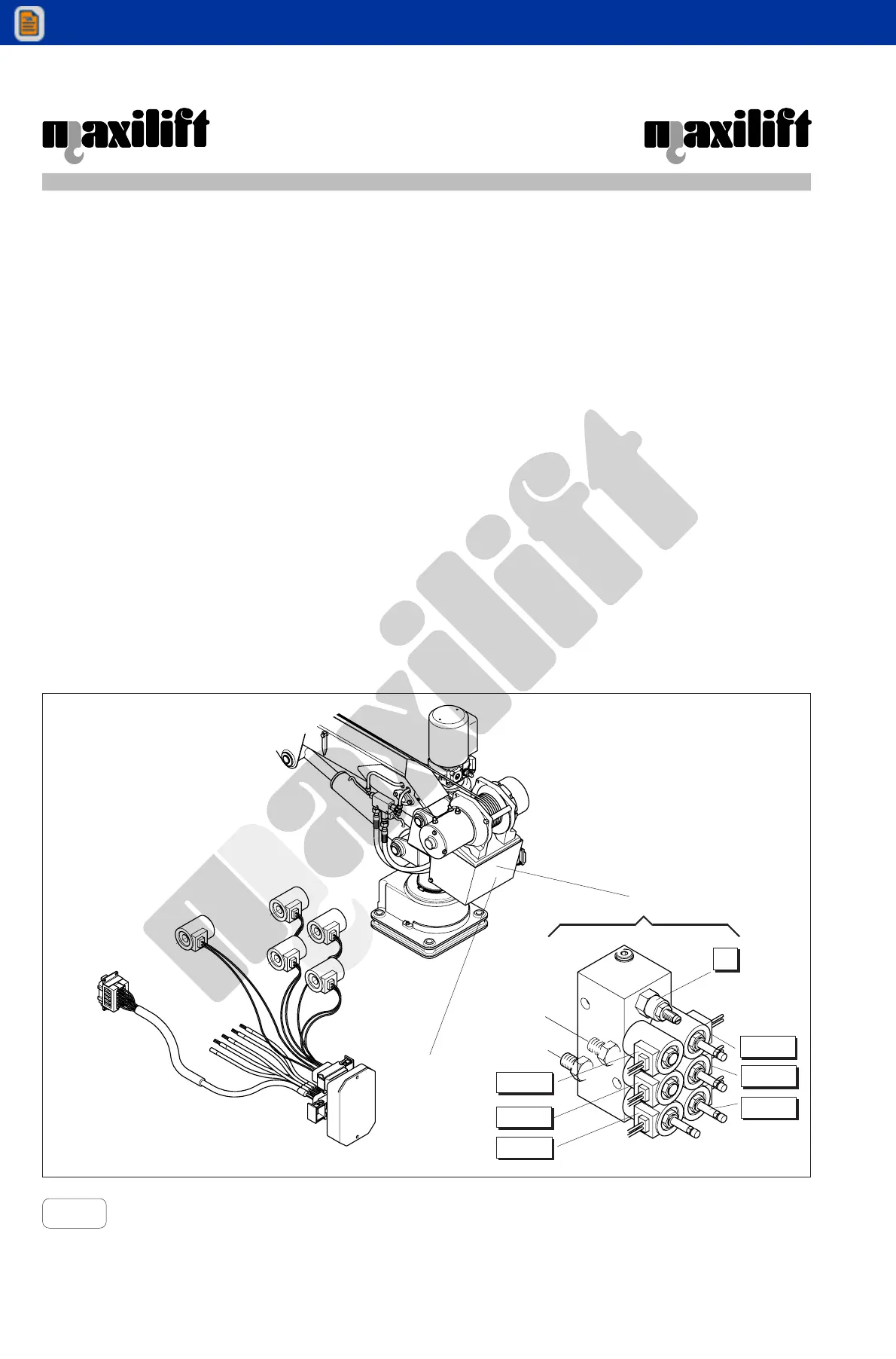
The remote control system includes a directional electro-hydraulic unit (manifold) (A) and a electronic power
unit (B), placed inside the casing behind the column, a remote control box and a wiring system.The electro-
hydraulic manifold includes an aluminium block equipped with directional electrovalves (EV..A-EV..B) (two
each mouvements), a main relief valve (5).
The electrovalves (EV3B-EV2B-EV1B-EV1A) are fitted with manual controls, to be used only in case of
emergency (remote control box or electronic power unit breakdown).
Model 3300W - E
For emergency manoeuvres, fully turn counter-clockwise the manual control of the electrovalve coupled to
the desired mouvement and let the electric power pack motor run temporaly, supplying directly relevant
relais by the prepared cable from the positive power terminal to the positive solenoid connection, momen-
tarly replacing the existing cable. This way, the motor run until the emergency cable is connected . Keep the
motor running only for the short periods required to carry out the emergency manoeuvres. Afterwards,
restore the original connection.
6.4.1 Electronic power unit
The electronic control unit, placed inside the near column casing, is a fully sealed component containing the
electronic parts with microprocessor logic, due to handle all crane movements and safety device. Two
connector for the guide connection to the solenoids and safety device cables jut out of it.
Pict. 7
B
A
5
EV3A
EV2A
EV1A
EV2B
EV1B
EV3B
Manifold