Maxim Integrated Page 12 of 52
MAX32664 GPIOs and RSTN Pin
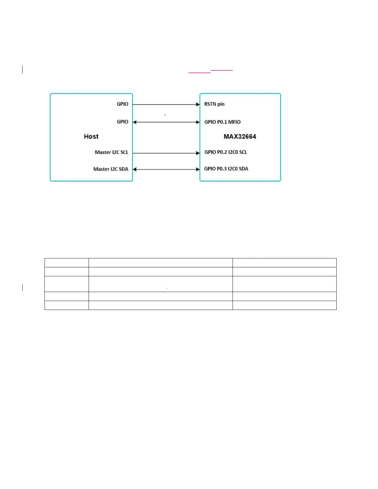
To control and communicate with the MAX32664, the RSTN pin and GPIOs P0.1, P0.2, P0.3 of the
MAX32664 are connected to the host as pictured in Figure 3Figure 3.
Figure 3. Pin connections between the host and the MAX32664.
The RSTN pin is used in conjunction with the GPIO P0.1 MFIO pin to control whether the MAX32664 starts
up in Application mode or Bootloader mode. While in application mode, the MFIO pin can be configured
to provide an interrupt signal to the host.
The host acts an I
2
C master to communicate with the MAX32664. GPIO P0.2 is used as the SCL line and
GPIO P0.3 is used as the SDA line.
Table 2. RSTN Pin and GPIOs Pins
GPIO MFIO interrupt to host, wake from host,
bootloader/application on powerup,
Variations of the MAX32664 use additional GPIO pins in order to communicate and control sensor devices.
For example, in the MAXREFDES220#, the additional GPIOs listed in Table 3 are used to control the sensors
used.